Fiber Optic PLC Splitter

Fiber optic splitter is an optical passive device used to realize the splitting and combining of optical signals. Fiber Splitter distributes the light energy which transmitted in one fiber to two or more fibers in a set ratio, or combines the light energy which transmitted in multiple fibers into a single fiber.


PLC splitter is Planar Light wave Circuit splitter based on optical semiconductor technology. It is one of the most important passive devices in passive optical network (PON), with multiple inputs and multiple outputs, commonly use MxN to indicate a splitter has M inputs and N outputs.The optical splitters used in fiber optic CATV systems are generally 1×2, 1×3, 1×4, 1×8, 1×9, 1×12, 1×16, 1×24, 1×32 and 1xN etc. PLC splitters are used to evenly divide one or two optical signals into multiple optical signals.

Application

PLC Splitter is widely used in FTTH and FTTx Networks such as BPON, GPON, EPON, and xG EPON to connect the MDF (main distribution frame) and the terminal equipment and to branch the optical signal.

International Standards

IEC61300-2, ROHS,GR-1209-CORE, GR-1221-CORE

RoHS stands for Restriction of Hazardous Substances, and impacts the entire electronics industry and many electrical products as well. The original RoHS, also known as Directive 2002/95/EC, originated in the European Union in 2002 and restricts the use of six hazardous materials found in electrical and electronic products. All applicable products in the EU market since July 1, 2006 must pass RoHS compliance.

IEC61300-2 is for fiber optic standards, for more details, please refer to below link:

https://webstore.iec.ch/publication/5161

An introduction to GR’s history and objective of implementation of the standard. Also touch on evolution of the standards (recently added requirements for anti-fungus) Telcordia GR1209 & GR-1221 standards outline the generic criteria for passive optical components to ensure continuous operation of the components over its lifetime. The standards specify performance tests to reflect a composite picture of various conditions. These compliance tests cover three main features of an optical splitter which are the general requirements for an outside plant component, the functional design criteria and its performance criteria. The environmental and mechanical tests outlined in the GR-1209 standard is designed to demonstrate the short term operational performance of a passive optical component. The normal lifespan of an FTTH network is at least 25 years, thus it is recommended for the environmental and mechanical test criteria to be based on the GR-1221 standard. The performance tests are intended to reflect a composite picture of various conditions. The generic criteria, desired features and test methods may be subject to change. Such changes or addition is done to enhance the reliability criteria of the passive component under test. An example of such an update is the inclusion of an anti-fungus test in the GR-1209 test standard.

Excerpted from: SENKO

PLC Working Principle

When a single mode fiber conducts an optical signal, the light energy is not concentrated in the core, there are a little of light will transit through the cladding layer. When the cores of two fibers are close enough, the mode field of the light transmitted in one fiber can enter the other fiber, and the optical signal is redistributed in both fibers.

Optical fiber splitter light transmission is bi-directional, also the loss value is inidependent of the transmission direction. Whether the optical signal is transmitted from the input of the optical splitter downstream to the output or from the output upstream to the input, the loss value is the same in both transmission directions. Therefore, we only need to measure the loss value in one direction of the optical splitter.

PLC chip is the key component of a fiber PLC splitter. It consists of three layers: a substrate, a waveguide and a cover. The waveguide plays a key role in the splitting process that allows a specific percentage of light to pass through. So the signal can be divided equally. It is available in 1xN (N=2, 4, 8, 16, 32, 64) and 2xN (N=2, 4, 8, 16, 32, 64) splitting ratios. The figure below shows the typical design of a 1×8 PLC splitter chip.

Factory Direct Price

No need searching on market every inquiry, no need bargaining every time for budget, no need worrying payment lost after swift. Yingda 15+years long term manufacturing and independent import and export rights and experience ensure all your rights and interests.

Manufacturing Process

Yingda have 2 dust free workshops for mass production with 50+workers, all segments are carefully designed with strict control of quality standards and standardized processes.  All our fiber optic splitters 100% test before delivery, and samples available

Classifications of PLC Splitters

Fiber optic splitter has a variety of classification methods, commonly have 3types: the connectors, packaging method, splitting ratio.

Method 1: By package

PLC splitters can be classified based on different packages to meet clients’ needs in various scenarios, including small size PLC splitter that needs to be used in terminal boxes, big size in racks or big distribution box. There are mainly 4 types of basic package:

Bare Fiber Splitter 250um

Mini Module Splitter 900um

ABS Module Splitter 2mm 3mm

LGX Modular Splitter

Basis package optical splitters can be used individually, also can be installed in different fiber optic box or fiber enclosures.

Splice Closure With Micro Splitter

Inline Splice Closure with Splitter

Optical Distribution Box with LGX splitter

Splitter Distribution Box with LGX splitter

Rack Mount Patch Panel with Splitter

19Inch Sliding Tray with Splitter

Fiber Termination Box with Splitter

Method 2: Split Ratio (Take Mini Splitter For Example)

PLC Fiber Optic Splitter can be categorized by the PLC splitter chip they use, meaning there are 1xN and 2xN PLC splitters, such as 1×4 splitter, 1×8 splitter, 1×16 splitter, 2×32 splitter, 2×64 PLC splitters, etc. Users can choose different input and output numbers depending on subscriber conditions or project requests.

1:2 PLC Splitter

1:4 PLC Splitter

1:8 PLC Splitter

1:16 PLC Splitter

1:32 PLC Splitter

1:64 PLC Splitter

1:128 PLC Splitter

2×2 PLC Splitter

2×4 PLC Splitter

2×8 PLC Splitter

2×24 PLC Splitter

Balanced Splitter

With the development of optical communications, the equal split taps can no longer meet the needs of various optical networks, there are many special applications and non-equal split scenario needs. The current market practice is to use different non-homogeneous 1×2 pull cone splitters with various homogeneous splitters to achieve the purpose of non-homogeneous splitting. This method is a 1×2 outgoing end and PLC tap incoming end fused together, fusion point using heat shrink tube protection. At the same time, we can also provide a more convenient and stable non-homogeneous solution for customers to use, is the direct use of non-homogeneous chip PLC splitter, currently available in mass production of 1X3, 1X5 and 1×9 splitter. If you need more information, please contact us for more information.

1:3 PLC Unbalanced Splitter

1:5 PLC Unbalanced Splitter

1:9 PLC Unbalanced Splitter

Unbalanced Splitter

Fastest Delivery Time

Complete supply chain, strictly ISO management system, enough stable skilled workers ensure full  high efficiency productivity, short lead time.

Package Information

Yingda can provide various packaging methods, such as bags, blister boxes, cardboard box with foam or bubble, etc. Also, according to different customers’ shipping requirements, design requirements or different application, we can customize different packaging methods. Welcome valuable ideas to improve the package performance.

1pc/PP bag, 500pcs/carton box

1pc/blister box, 250pcs/carton box

10pc/inner box, 200pcs/carton box

STEEL TUBE SIZE

Yingda has been specialized in manufacturing splitters for more than 10 years, and can be customized according to customer needs:  label, split ratio, tag, tube size, inlet and outlet pigtail length or color, connectors, pacakage, etc.

PIGTAIL COLOR / LENGTH
LABEL ON PRODUCT
CONNECTORY TYPE
TEST REPORT DESIGN

Quality Assurance

The GR-1209 standard provides comprehensive optical performance criteria for a passive optical splitter.

There are 5 main specification that is outlined in this standard.  See left details.

The optical bandpass can be tested by connecting the optical splitter to a optical spectrum analyzer with a high power light source havig a central wavelength of the required bandpass. The attenuation across the required bandpass shall meet the splitter requirements.
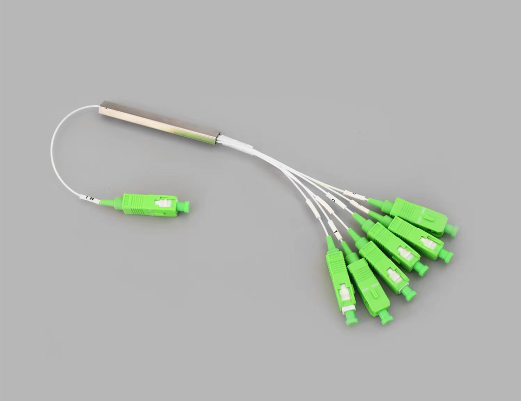
1 of 5

Tested by using a light source ad power meter. The reference power level is obtained and each of the output port of the optical splitter is measured.
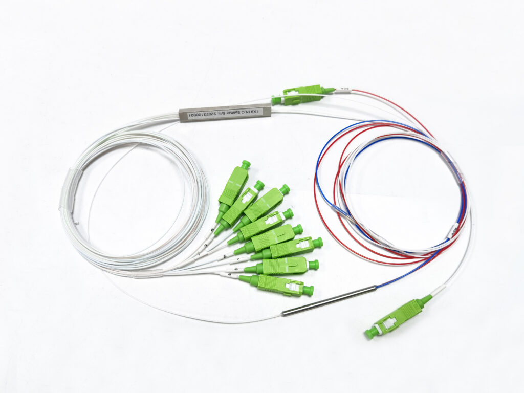
2 of 5

Determined by referring to the results from the insertion loss test to ensure that the difference between the highest loss and the lowest loss within the acceptable uniformity value.
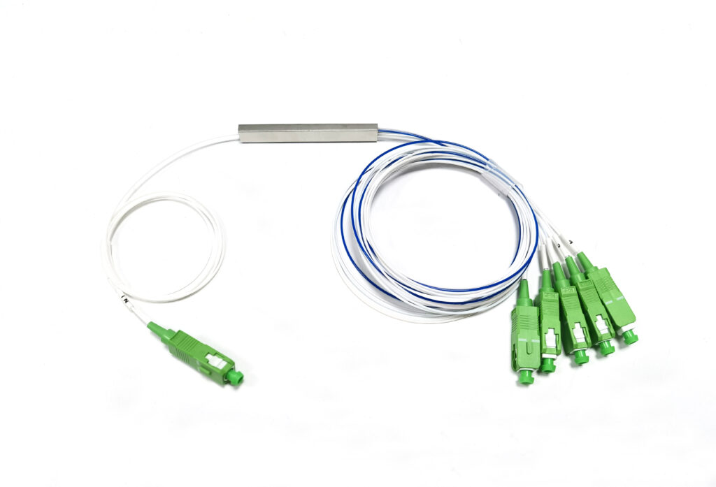
3 of 5

Tested by a rerun loss meter. The input port of the splitter is connected to the return loss meter and all the ouput ports are connected to a non-reflective index matching gel.
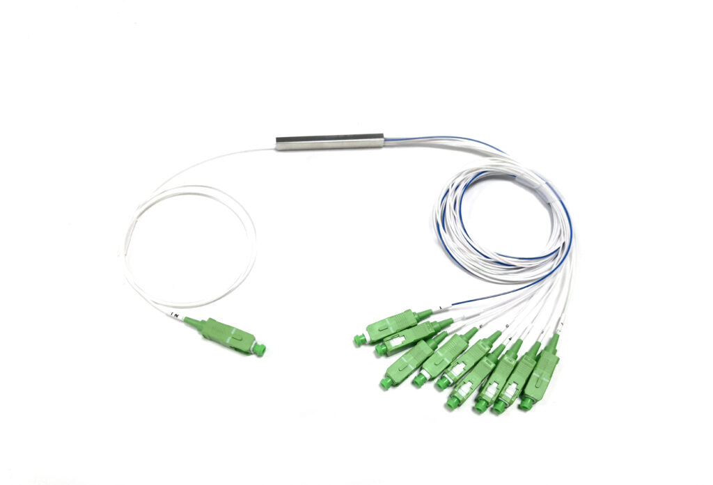
4 of 5

Measured into a manner similar to the insertion loss test. However, the light source and power meter are connected to each of the input ports of two outputs ports.

5 of 5

Please help offer below information in details, offer wil be answered asap.

24 hour/7dasy supporting service!

Do You Want Instant Help ? Free Quote ?

FAQ (About PLC Splitter)

YINGDA can provide pre-sales, in-sales and after-sales services in all aspects. As a customer, in the process of using fiber optic splitter, all  hope that there is no problem, but if you encounter problems, please contact our company in time, we guarantee that in the shortest possible time to provide a variety of professional solutions, so that customers can be rest assured from the problem.

Pls check if there is fiber broken input or output pigtails, if fiber broken, you see clearly the light come out, if not, there should be problem on the plc chip. Inside the 2 fiber array is not docked with the chip in place(not aligned with each other); curing glue off,  using poor quality glue or glue is not enough, curing process is not qualified.

— Yingda use imported glue with strict quality management, and the glue is replaced regularly every day, and we will not use it after the expiration date. And all of our products use original AT6001 (NTT) coupling glue and 353ND epoxy glue, 100% full inspection before delivery, so this problem is completely eliminated.

Fiber fracture mainly resulted by fiber excessive bending a lot during packaging process. Bad packaging, such as bags or many pieces pack together, easily lead to extrusion deformation breakage, or the bend radius is not reasonable.

During the transportation process due to the packaging protection is not enough or not in place, excessive upside-down shaking so that the product shifts seriously, resulting in dislodgement.

So highly recommend customers to use blister box or foam in carton box packaging, reasonable bending radius and winding angle will not cause this problem.

If the product is independent, make sure to confirm the parameter requirements with the customer before order. Production , QC and QA will strictly follow the standard execution, quality unqualified resolutely not shipped.

If optical fiber splitter is assembled with other products and the parameters are found to be incorrect, pay attention to whether the other products are not qualified. For example, installed into the adapter, the adapter sleeve rupture, resulting in the insertion of fiber optic head is damaged or worn. Therefore, the choice of related products also need to pay attention to quality assurance. All our supporting adapters are from China TOP 1 factory and zicronia ferrule are from three circle, refuse to inferior products, which only look at the price not care about the quality.  

As known that, fiber color code is to distinguish each multi-fibers, but if pigtails all white not colorful, it should use number rings to distinguish each channels, then wearing wrong or duplicate number rings on pigtails is possible and easy to confused. How do we solve this problem?

  1. We created a very detailed point-to-point production specification, listing clearly how to wear number rings one by one, make complicated things to small pieces simply, take 1x8plc splitter for example.
  • Input: Original
  • Output: 2*4 Color (Blue/Orange/Green/Brown)left to right
  1. Each step of productionis operated by different personnel to supervise each other, which can effectively find and avoid this problem.

If you receive the goods and find that there is water vapor, it means that the end face is not cleaned well after grinding or maybe polluted by dust cap or related products.

All our products are produced in clean dust-free workshop, 100% end inspection twice, there will be no fiber end breakage or spoil situation. Twice check is also to prevent the water if not dry and delivered.

Our number tube is made of new HYTREL material, not second-hand material.There are some factory may use bad quality plastic tubes instead, which will change during different temperature or climate change.

Hytrel is a thermoplastic polyester elastomer material that is a class of block copolymers containing a polyester hard segment and a polyether soft satin synthesis. The material combines many desirable properties of high-performance elastomers and flexible plastics, demonstrating excellent toughness and elasticity, high creep resistance, abrasion resistance, impact and flexural fatigue resistance, flexibility at low temperatures, and good performance at high temperatures. In addition, hi can resist oil, chemical solvents, etc. Due to the comprehensive properties of hytrel such as outstanding mechanical strength, excellent resilience and wide service temperature, it is suitable for many demanding applications that require flexibility missing mechanical strength and durability, including seals, bushings, sleeves and impact resistant devices. Due to the excellent overall performance of the above materials, in some scenarios to be more advantageous than traditional casing materials for fiber optic protection.

Manufacturers do not do high and low temperature cycle test, the glue used is not good or the production process is not qualified. Our products go through several UV curing operations, all did through -40 ~ +850C high and low temperature cycles(though it may take too much time, but for quality reasons, it is worthwhile).All glue epoxy are original imported to ensure that all products in extreme adverse conditions can work properly.

What Is The Difference of FBT Splitter ? PLC Splitter ?

The PLC splitter is based on planar optical wave circuit technology. It consists of three layers: a substrate, a waveguide and a cover. The waveguide plays a key role in the splitting process that allows a specific percentage of light to pass through. So the signal can be divided equally. In addition, PLC splitters are available in a variety of splitting ratios, including 1:4, 1:8, 1:16, 1:32, 1:64, etc. They are also available in various types, and the following table shows the advantages and disadvantages of PLC splitters.

The FBT splitter is based on a conventional technique where multiple fibers are welded together from the side of the fiber. The fibers are aligned by heating to a specific position and length. Since the fused fibers are very fragile, they are protected by a glass tube made of epoxy resin and silica powder. The inner glass tube is then covered with a stainless steel tube and sealed with silicon. As technology continues to evolve, FBT splitters are of very good quality and can be applied in a cost effective manner. The table below shows the advantages and disadvantages of FBT splitters.

PLC Inner Structure

Advantages:

  • Applicable to the full waveband 1260-150nm, a wider range of applications
  • All output channels are equally divided
  • Compact configuration, smaller size, smaller footprint
  • All channel splitting ratio has good stability because it is pre-distributed by the chip
  • Maximum 1:128 splitting ratio can be achieved
  • High quality, low failure rate
  • Temperature range:-400C ~+850C


Disadvantages

  • Complex production process
  • 1:2 is more expensive than FBT splitter
FBT Inner Structure

Advantages

  • Easily available and cheaper materials
  • The splitting ratio can be customized and not fixed.

Disadvantages

  • Limited by operating wavelength, only 850nm, 1310nm, 1490nm, 1550nm
  • Maximum insertion loss varies by splitting and increases significantly for splitters over 1:8.
  • The transmission distance will be limited as the exact ratio cannot be guaranteed.
  • The temperature range is narrower than PLC, and the loss with high and low temperatures is relatively large
  • Prone to failure due to extreme temperatures or improper handling
  • 1:4 and above is more expensive than PLC
  • Maximum can only do 1:32

More Comparasion

1. Working wavelength

The FBT spectrometer only supports three wavelengths: 850nm, 1310nm, and 1550nm, which makes it impossible to work at other wavelengths. the PLC spectrometer can support wavelengths from 1260 to 1650nm. The adjustable wavelength range makes the PLC spectrometer suitable for more applications.

2.Splitting Ratio

The split ratio is determined by the input and output of the fiber optic splitter. fbt splitters have a maximum split ratio of up to 1:32, which means that one or two inputs can be split into a maximum of 32 fibers for the output. However, PLC splitters have split ratios of up to 1:64 – one or two inputs with a maximum output of 64 fibers. In addition FBT splitters are customizable, with special models such as 1:3, 1:7, 1:11, etc. But PLC splitters are not customizable, only standard versions such as 1:2, 1:4, 1, etc.:8, 1:16, 1:32, etc.

3. Asymmetric attenuation of each branch

The signal processed by the FBT splitter cannot be evenly split due to the lack of management of the signal, which affects the transmission distance. But PLC splitter can support equal splitting ratio of all branches, which can ensure more stable optical transmission.

4. Failure Rate

FBT splitters are typically used in networks that require a tap configuration with fewer than 4 taps. The larger the split, the greater the failure rate. When its split ratio is greater than 1:8, more errors occur, resulting in a higher failure rate. Therefore, FBT splitters are more limited by the number of splits in a coupling. However, PLC splitters have a much smaller failure rate.

5. Temperature Related Losses

In some regions, temperature can be a critical factor affecting the insertion loss of optical components. FBT splitters are stable at temperatures from -5 to 75°C. PLC splitters can operate over a wider temperature range of -40 to 85°C, providing relatively good performance in extreme climatic regions.

6. Price

PLC taps generally cost more than FBT taps due to their complex manufacturing process. If you have a simple application and are short on funds, FBT splitters can provide a cost effective solution.

How To Use PLC Splitter In PON Network ? FTTH Network ?

Optical splitter is the core optical device in passive optical network (PON) system, widely used in fiber-to-the-home (FTTH), which has two different distribution methods in FTTH network: centralized distribution and cascaded distribution.

Centralized distribution

Centralized distribution means that the optical splitters between optical line terminal (OLT) and optical network unit (ONU) are in parallel, basically in the form of “OLT → optical splitter → ONU”, where the splitting ratio of optical splitter is usually 1:32. In centralized distribution, the optical splitters are centrally distributed in fiber optic distribution boxes and In centralized distribution, optical splitters are centrally distributed in fiber optic distribution boxes and connected directly to the OLT at the central office through a single fiber, while the other end is connected to multiple ONTs at the subscriber end through multiple fibers. Its use is generally divided into four cases:

  1. placed in the bureau-end server room.
  2. placed in the cell room.
  3. placed in the cell optical handover box.
  4. directly placed in the building.

Centralized distribution has the advantages of high flexibility, low cost and easy maintenance, and is generally suitable for use in the city center or town with a high concentration of users.

Cascaded distribution

Cascaded distribution means that the optical splitters between optical line terminals (OLTs) and optical network units (ONUs) are cascaded, basically in the form of “OLT → optical splitter 1 → optical splitter 2 → ONU”, where the splitting ratio of optical splitter 1 is usually 1:4 and that of optical splitter 2 is usually 1:8. In cascaded In cascaded distribution, optical splitter 1 is usually installed near the central office, and optical splitter 2 is usually installed near the user side, such as in the building. Its use is generally divided into three cases.

  1. primary optical splitter is placed in the bureau-end server room, and secondary optical splitter is placed in the cell optical handover box.
  2. primary optical splitter placed in the cell room, secondary optical splitter placed in the cell optical handover box.
  3. The primary optical splitter is placed in the cell optical handover box, and the secondary optical splitter is placed in the building.

Cascade distribution has the advantages of low user access cost and flexible adjustment of splitting ratio, generally suitable for use in villages with more dispersed users.

Difference Centralized Splitting vs Cascading Splitting ?

Optical fiber splitter can be placed at different locations in a PON based FTTH network, which involves using either a centralized (single-stage) or cascaded (multi-stage) tap configuration in the distribution portion of the FTTH network. In fact, both approaches have their own advantages and disadvantages. So which one should you deploy? Below are comparison

Centralized Splitting

Centralized distribution typically uses a combined split ratio of 1:64, 1:2 splitters at the local end, and 1:32 in the cabinet. these single-stage fiber splitter can be placed in multiple locations in the network or installed in a central location. In most cases, however, centralized plc splitter are placed in the external plant (OSP) to reduce the total amount of fiber required. The active port of the OLT (optical line terminal) in the central office (CO) will connect/splice to the fiber leaving the CO. The fiber passes through a different enclosure to the input port of a fiber optic splitter that is normally placed in the cabinet. The output port of this fiber splitter enters the FTTH distribution network and reaches the potential customer’s home through different enclosures and indoor/outdoor terminal boxes called ONTs (Optical Network Terminals). Thus, in this centralized split topology, the PON connects one OLT port to 32 ONTs.

Cascading Splitting

The cascaded splitting method has no fiber splitter at the central office. The OLT ports are directly connected/spliced to the external plant fiber. The first stage splitter (1:4 or 1:8) is installed in a closed location not far from the central office. The input of the first stage fiber splitter is connected to the OLT fiber from the central office. The second stage fiber taps (1:16 or 1:8) are located in a termination box very close to the customer’s location, covering 8 to 16 homes per tap. The input to these PON taps is the fiber from the output of the first stage taps described above.

From above description, it is clear that in a centralized split network, all PON Splitters are located in a closed closure, which will maximize OLT utilization and provide a single point of access for troubleshooting. However, since the splitter must be terminated to the customer via separate connectors or splices, the cost of distribution cables will be very high.

In cascaded splitting, PON splitters are located in two or more different closures, which minimizes the number of fibers that need to be deployed to provide service. However, this can result in inefficient use of OLT PON ports and may increase testing and turn-up time for customers.

How To Choose Centralized Splitting Or Cascading Splitting ?

FTTH network architecture will depend on a variety of factors, except the deployment difference of centralized vs. cascading, your budget and expected future scalability will be considered too.

In addition, the density of your customer base is one of the most important deciding factors. In urban areas, distributed splitting will be the best option to quickly scale and connect many customers. On the other hand, a centralized split is better given the flexibility of rural or less populated areas.

Keep In Touch

Pls write down your questions or inquiry, will get back to you within 24hours. Thanks for your time!