Skip to content


Description
Fiber Splitter 2×24 Features
- High uniformity
- Low insertion loss
- Compact & small size
- High reliability and stability
- Optional input & output pigtails, connectors and length
- Single Mode Fiber Type G657A
Fiber Splitter Specification
| Split ratio | 1×2 | 1×4 | 1×8 | 1×16 | 1×32 | 1×64 | 1×128 | 2×2 | 2×4 | 2×8 | 2×16 | 2×32 | 2×64 | ||||
| Operating Wavelength (nm) | 1260-1650nm | ||||||||||||||||
| Fiber Type | G657A1 or customer specified | ||||||||||||||||
| Insertion Loss (dB)S Grade | 4.2 | 7.6 | 10.7 | 14 | 17.2 | 20.8 | 24 | 4.4 | 8 | 11 | 14.6 | 17.8 | 21 | ||||
| Insertion Loss (dB) P Grade | 4 | 7.4 | 10.5 | 13.8 | 17 | 20.4 | 23.7 | 4.2 | 7.7 | 10.8 | 14.1 | 17.4 | 20.7 | ||||
| Loss Uniformity(dB) | 0.6 | 0.8 | 0.8 | 1.0 | 2.0 | 2.0 | 2.0 | 0.8 | 1.0 | 1.2 | 1.5 | 1.8 | 2.0 | ||||
| PDL(dB) | 0.2 | 0.2 | 0.3 | 0.3 | 0.3 | 0.4 | 0.5 | 0.2 | 0.2 | 0.3 | 0.3 | 0.3 | 0.4 | ||||
| Return Loss (dB) | 55 | ||||||||||||||||
| Directivity (dB) | 55 | ||||||||||||||||
| Wavelength Dependent Loss(dB) | 0.6 | 0.8 | 0.8 | 1.0 | 1.5 | 2.0 | 0.2 | 0.8 | 1.0 | 1.2 | 1.5 | 1.8 | 2.0 | ||||
| Operating Temperature | -40- +85℃ | ||||||||||||||||
Details of Fiber Splitter 2×24
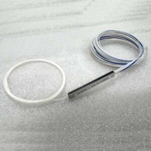
The splitter 2×24 is initially placed in a transparent plastic tray, which helps protect the delicate fibers and the splitter module during storage and transportation, preventing any potential damage.
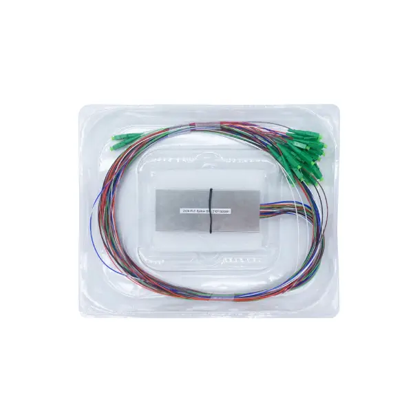
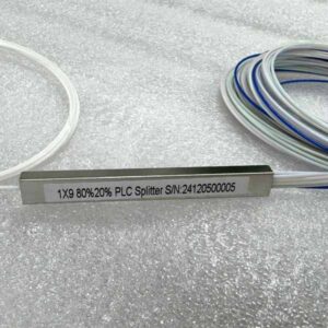
It features a metallic rectangular module. On this module, there is a label that clearly identifies it as a “2×24 PLC Splitter”, along with a serial number for individual tracking.
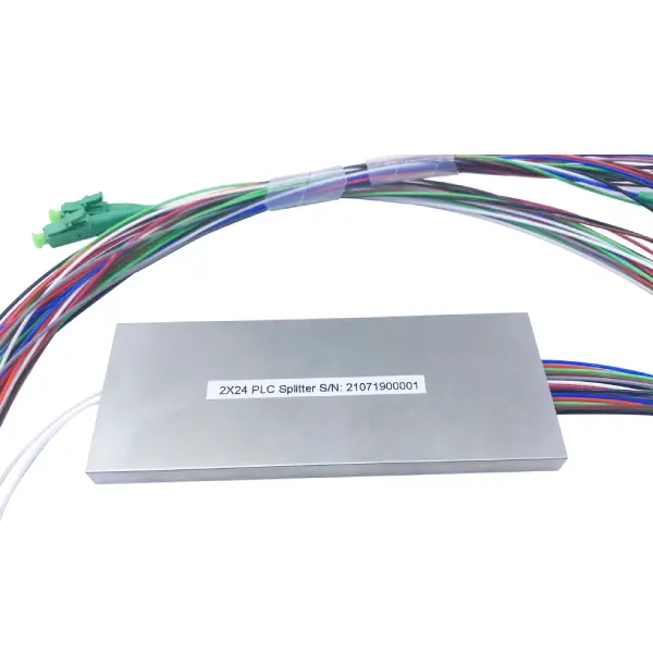
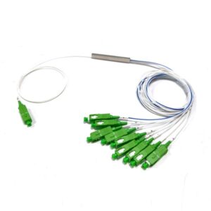
AS a 2×24 unbalanced splitter, it takes 2 input optical signals and splits them into 24 output signals with unequal power distribution among the outputs. This unbalanced splitting capability allows for flexible allocation of optical power in optical networks, catering to different network design requirements where different nodes or devices may need varying amounts of optical signal strength.
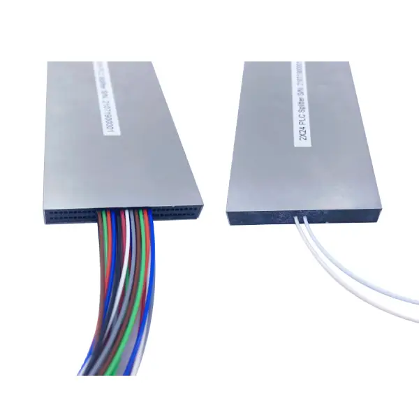
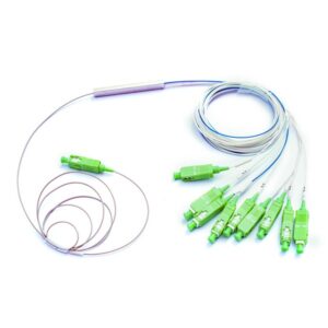
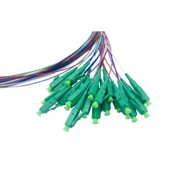
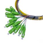
Regarding the optical fibers, there are multiple colored fibers (such as red, blue, green, etc.) connected to the splitter. These fibers are responsible for transmitting optical signals. At the ends of the fibers, there are green LC/APC connectors. These connectors are designed for precise and secure connection to other optical components, ensuring minimal signal loss during transmission.
Recommended Products
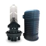 |  |  |
| Professional GJS-D023 Optic Fiber Splice Closure | Optical Fiber LC Connector 1.2mm Boot | 12 Core High Density Fiber Optic Pigtail |