 Skip to content
 PON is the main technology used for fiber optic broadband access. It has been 15 years since China Telecom began large-scale commercial use in 2006, but the application of PON technology has not declined at all. It is not only the main technology for fiber optic broadband access, but also gradually penetrating into private networks, local area networks, and home internal networking.
The Meaning of Passive Optical Networks
PON is the abbreviation of Passive Optical Network. PON technology connects multiple users simultaneously through one optical fiber. Before the emergence of PON technology, other optical access technologies had to implement the same functions, and active convergence equipment existed in ODN. PON technology uses passive optical splitters to replace active convergence equipment. There is no active equipment in ODN, so this technology is called a passive optical network. That is to say, a passive optical network means that the ODN part is passive.
PON consists of optical line terminal OLT, optical distribution network ODN, and optical network unit ONU.

OLT is central office equipment. User equipment includes ONTs and ONUs.
- ONT is an optical network terminal, usually used by a single user, also commonly known as optical modem. FTTO and FTTH user terminals belong to ONT.
- ONU is usually shared by multiple users and is mainly used in FTTB. User equipment can also be collectively referred to as ONU.
For details on the differences between different types of ONUs, see the article “What are the differences between ONU, ONT, SFU, HGU…”.
ODN refers to the passive optical distribution network composed of access optical cable lines and optical splitters between OLT and ONU. For details on the networking of access optical cable lines, please refer to the article “Optical distribution Network Structure”. For details on the setting of optical splitters, please refer to “The Difference between Primary Splitting and Secondary Splitting in ODN and their application” article.
Key components of PON: optical splitter
Optical splitter is a key component in PON. It is a passive component based on optical power splitting. It can divide one optical signal into multiple channels and complete the reverse process.
The picture above shows a 1×2 splitter. When one optical signal enters, it is divided into two identical signals. The optical power of the split signal is only half of the original signal. Cascade a 1×2 splitter once to become 1×4, and cascade it again to become 1×8… The splitting ratios of our commonly used optical splitters are 1×4, 1×8, 1×16…. In FTTR, a 1×5 optical splitter with unequal split ratio is also used.
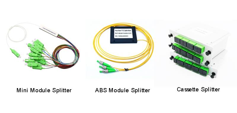
Depending on finished products package difference, splitters are mainly divided into three types: Mini type, ABS module type and cassette type (LGX module).
- Mini module type is the simplest type with stainless steel tube with 900um loose tube at both sides with connectors or without connectors, it can be used in most of fiber distribution boxes or joint clousres, rack patch panel, etc due to its small size, and large splitting ratio.
- ABS module type splitters are also called pigtail type with a plastic black box to hold the mini module steel tube inside, and the input and output pigtails normally are 2mm diameter, which is better protection for the fiber, and are mainly used in optical cable distribution boxes or closures too;
- Cassette type splitters are also called connector types, there is mini module splitter inside too, then with adapters on the cassette box to hold it in place, and are mainly used in optical fiber distribution boxes too.
Each time the splitting ratio of the splitter increases by 1 level, the insertion loss increases by approximately 3dB. For a splitter with the same splitting ratio, the insertion loss of the cassette type is about 0.2dB greater than that of the ABS module type.
| Splitter specification | Insertion loss (typical) Unit:dB | Insertion loss (typical) Unit:dB |
| ABS module type | Cassette type | |
| 1×2 | 4.2 | 4.4 |
| 1×4 | 7.8 | 8.0 |
| 1×8 | 10.9 | 11.1 |
| 1×16 | 13.9 | 14.1 |
| 1×32 | 17.2 | 17.4 |
| 1×64 | 20.9 | 21.2 |
Technical principles of PON
The downlink of PON (from OLT to users) uses the broadcast method. The optical splitter broadcasts the downlink optical signal to each ONU connected to the same splitter. Each ONU receives its own signal and discards the signal that does not belong to itself.

The uplink of PON uses time division multiplexing (TDM), and each ONU communicates with the OLT in different time slots.
PON uses different wavelengths for uplink and downlink. OLT and ONU adopt optical transceiver-integrated optical modules to transmit different wavelengths in one optical fiber.
Differences between different PON technologies
The PON technologies currently used mainly include EPON and GPON, as well as 10G-EPON and XG-PON. Although there are great differences between different PON technologies, from the perspective of users, the main differences are in line speed, available bandwidth and working wavelength.
| Item | EPON | GPON | 10G-EPON (Asymmetric) | 10G-EPON (symmetry) | XG-PON | XGS-PON |
| Technical standards | YD/T 1475 | YD/T1949 | YD/T 2274 | YD/T 2274 | YD/T 2202 | YD/T 3691 |
| Line rate (Mbps) downlink | 1250 | 2488 | 10312.5 | 10312.5 | 9953 | 9953 |
| Line rate (Mbps) uplink | 1250 | 1244 | 1250 | 10312.5 | 2488 | 9953 |
| Available bandwidth(Mbps)downlink | 950 | 2200 | 8300 | 8300 | 8500 | 8500 |
| Available bandwidth(Mbps)uplink | 900 | 1100 | 900 | 8000 | 2000 | 8500 |
| Working center wavelength(nm)downlink | 1490 | 1490 | 1577 | 1577 | 1577 | 1577 |
| Working center wavelength(nm)uplink | 1310 | 1310 | 1310 | 1270 | 1270 | 1270 |