Fiber optic cable connectors are widely used connecting components in optical communications. The successful connection of optical fiber lines depends on the quality of the physical connection of fibers. In order to improve the efficiency of fiber optic connections and optical signal transmission, the geometric dimensions of the fiber optics connectors end face must be strictly controlled to reduce insertion loss and return loss. If the end face geometric dimensions are not strictly controlled, or the geometric dimensions cannot meet the requirements, there will be a huge risk of system connection failure, and there will be no long-term reliable connection to the network.
Therefore, three-dimensional end-face inspection is not only a necessary step for end-face inspection of high-standard optical fiber connectors, but also has important guiding significance and reference value for the design and manufacturing of the device itself. The quality of the connector end-face is inseparable from its design and manufacturing process.
At the same time, based on the three-dimensional inspection results of the end face, the process can be improved and perfected:
① If the radius of curvature of the ferrule is too large, the grinding pad may be too hard; if the radius of curvature is too small, the grinding pad may be too soft. Therefore, the radius of curvature can be improved by adjusting the hardness of the polishing pad.
② If the amount of eccentricity is large, it may generally be caused by the large radius of curvature of the ferrule. On the other hand, the reason may be that the glue is not completely removed and some glue remains on the end face, causing the end face to be uneven. During grinding, the angle shifts, causing eccentricity.
③ If the optical fiber is dented, it may be that the polishing time is too long. The polishing time can be appropriately reduced. On the contrary, the polishing time can be appropriately extended.
What is end face 3D inspection?
According to the IEC standard, three technical parameters are generally specified for PC fiber optic connector: radius of curvature ROC, vertex offset and fiber height.
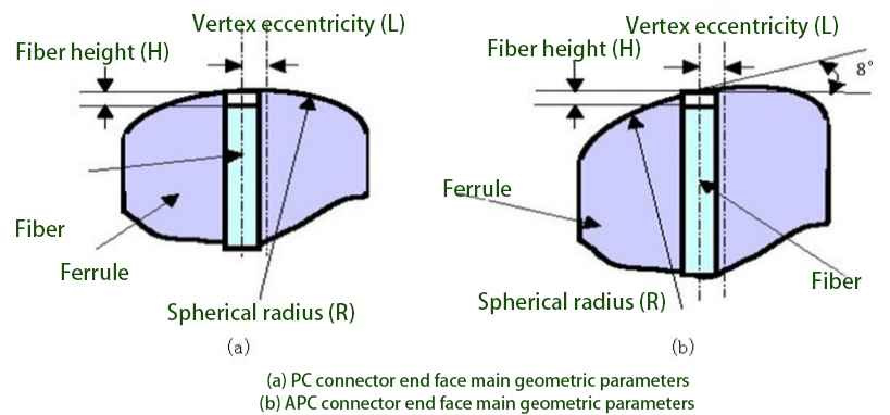
Radius of Curvature
The radius of curvature of the arc-shaped end surface grinding. Table 1 summarizes the relevant technical standards given by the IEC organization. The ROC should be of an appropriate size (10~25mm for PC-type connectors and 5~15mm for APC-type connectors). If the ROC is too large, it will not be able to produce enough deformation under pressure to ensure physical contact between the optical fibers. If the ROC is too small, the optical fiber will be easily crushed after repeated plugging and unplugging.
| End face | Radius of curvature ROC(mm) | Apex of curvature(um) | Fiber height (nm) |
| PC | 10-25 | ≤50 | -250 ~+250 |
| APC | 5-15 | ≤50 | -250~+250 |
Table 1. Technical standards for ferrule end face shapes formulated by the IEC organization
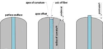
Apex Offset
Apex Offset refers to the offset between the surface apex and the fiber axis. Figure 3 shows the impact of apex offset on the physical contact between optical fibers. If the apex deviation is too large, the deformation of the end face is enough to cause physical contact between the optical fibers. Therefore, the technical standards require that the apex deviation of the fiber jumper is ≤50 μm.
Fiber Height
Fiber Height refers to the height of the fiber end face relative to the ferrule end face. The fiber end face may be protruding above the ferrule end face, or it may be recessed below the ferrule end face. A slightly smaller optical fiber dent will not affect the physical contact between the optical fibers, because the ferrule will deform to a certain extent under pressure; a slightly smaller optical fiber protrusion will not affect the physical contact between the optical fibers, because the optical fiber itself has a certain degree of elasticity. Therefore, the technical standards stipulate that the optical fiber height range is -250~+250nm.

In the technical standards in Table 1, we note that the radius of curvature of the APC type optical fiber connector is smaller than that of the PC type connector. APC connectors are prepared through a grinding disc at a certain angle. Figure 4(a) depicts the oblique arrangement of the ceramic ferrules in the grinding disc. However, when the ferrule is inserted into the ceramic sleeve of the adapter, its arrangement direction is vertical, as shown in Figure 4(b), and the apex of the curved surface will deviate from the core. Figure 5 describes the connection adaptation situation between two APC connectors. Since the vertices of the two end faces cannot be aligned, greater deformation of the ferrule end face is required to ensure physical contact between the fiber end faces. Therefore, the end face curvature radius of APC optical fiber connectors is required to be smaller.
case-in-the-grinding-disc-b-case-in-the-ceramic-sleeve-of-the-adapter.jpg)
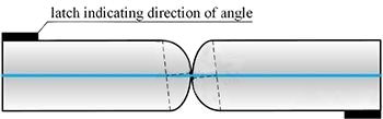
As shown in Figure 5, on an APC optical fiber connector, no matter what the specific model of the connector is, there is always an directional pin indicating the direction of the bevel. The indication accuracy of the directional pin will affect the apex offset of the APC connector. In addition, the error in the end face grinding angle will also affect the vertex offset.
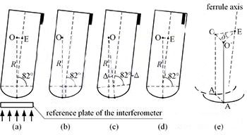
Figure 6 describes the vertex offset caused by various factors, where R is the radius of curvature of the end face, and point O is the center of curvature of the end face. The common vertex offset of the connector end face is shown in Figure 6(b), which is usually produced during the grinding process. As shown in Figure 6(c), if there is an error Δ in the end face grinding angle, when the ferrule is inserted into the 8° fixture of the interferometer, the eccentricity d1 = R·Δ will be measured. Note that the measurement conditions of the interferometer are consistent with the actual application of the fiber optic connector.
In Figure 6(d), the connector pin has an azimuth angle error δ, which may be introduced by mechanical components or assembly processes. When this kind of connector with azimuth error is inserted into the adapter, the ceramic ferrule deflects, and the center of curvature of the end face deflects from point O to point O’, while the apex of the end face deflects from point A to point A’, as shown in Figure 6(e). From Figure 6(d), we can know that the line segment length OE=R·sin8°, and then from Figure 6(e), the vertex offset caused by the pin azimuth error is d2=R·sin8°·sinδ.
Here is an example. Assume that the curvature radius of the connector end face is R=10mm, the grinding angle error is Δ=0.1°, and the pin azimuth angle error is δ=1°. From this, the vertex offsets caused by various factors are d1=17.5μm and d2=24.3μm respectively. Note that the IEC standard stipulates that the upper limit of vertex offset is 50μm.
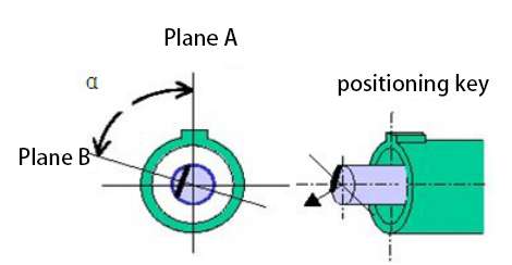
In addition to the three parameters mentioned above, there are two other parameters that need to be measured for the APC end face: APC angle (usually based on 8 degrees) and positioning key angle (Key Error).
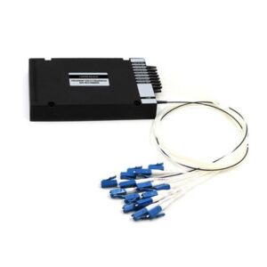
In addition, measuring the core dip on the fiber surface of multi-core MTP/MPO fiber connectors is of great significance. Due to the softness of the fiber core relative to the cladding material, it is easier to be cut during the grinding process, resulting in a depression in the fiber core (relative to the cladding), known as the “Core Dip”.
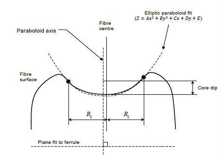
The internal depression of the fiber core can cause an “Air Gap gap” between the fibers when terminating MTP/MPO products, which directly (mainly) affects the system’s “Return Loss” indicator.
The correspondence between Core Dip index and Return Loss return loss is shown in the following table, where positive values of Core Dip index indicate “concave” and negative values indicate “convex”. Return Loss is defined as the docking test of MTP/MPO products of the same specifications, rather than direct reflection of air.
| Core Dip (nm) | Return loss (dB) |
| >150nm | <20dB |
| 0~150nm | 20~40dB |
| <0nm | >40dB |