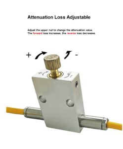
Description
Attenuator are widely used in cable television systems to meet the level requirements of multiple ports. For example, the control of the input and output levels of an amplifier, and the control of the branch attenuation. In the comparison method measurement circuit, it can be used to directly read the attenuation value of the measured network and improve impedance matching. If some circuits require a relatively stable load impedance, an attenuator can be placed between this circuit and the actual load impedance to buffer the impedance changes.
Features
- Reliable performance, stable attenuator technical indicators meet industry standards
- All-fiber structure, good environmental stability, low polarization-related loss
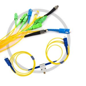
- Different styles of connectors
- Can effectively suppress ground loop noise and eliminate interference
- Effectively isolate from the main control end in electricity to prevent accidental damage to the main control end
- Plug-in times greater than 10,000+, good flame retardancy, reaching UL94V0, high temperature resistance and environmental protection, compliant with ROHS requirements, and high impact resistance.
Technical Parameters
| Item | Unit | Value | |||||
| Fiber type | / | S=single mode, P=PM fiber | M=multimode | ||||
| HI-780
PM780 |
HI-1060
PM980 |
SMF-28
PM1310 |
SMF-28
PM1550 |
SMF1950
PM1850 |
50/125
62.5/125 |
||
| Central wavelength | Nm | 780±10
850±10 900±10 |
980±20
1064±20 |
1310±30 | 1480±30
1560±50 |
1480±50
2000±50
|
850±40
1310±40
|
| Insertion loss without connector | dB | ≤1.3 | ≤1.0 | ≤0.6 | ≤0.6 | ≤0.7 | ≤0.8 |
| Insertion loss with connector | dB | ≤2.1 | ≤1.6 | ≤0.9 | ≤0.9 | ≤1.0 | ≤1.3 |
| Polarization film dispersion | dB | ≤0.05 | ≤0.05 | ≤0.05 | ≤0.05 | ≤0.05 | ≤0.15 |
| PER polarization only | dB | ≥18 | N/A | ||||
| Return loss | dB | ≥50 | ≥20 | ||||
| Attenuation | dB | ≥30 | |||||
| power | ≤300 | ||||||
| Working temperature | ℃ | 0~70 | |||||
| Storage temperature | ℃ | -40~+85 | |||||
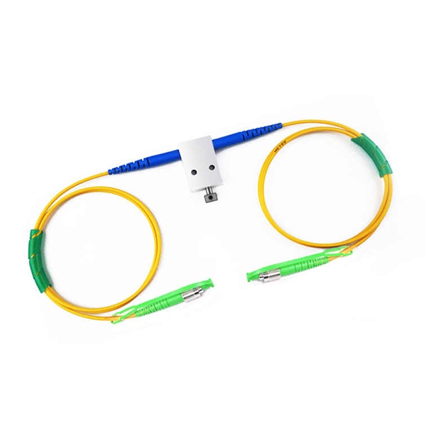
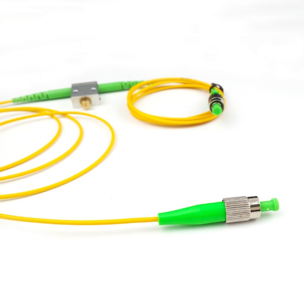
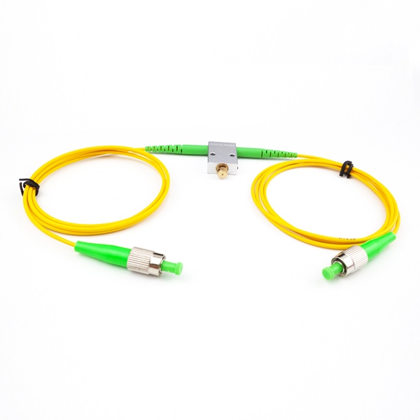
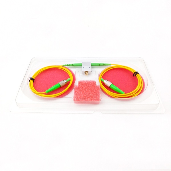
Detailed Display


Reviews
There are no reviews yet.