 Skip to content
 Due to different construction conditions and requirements, communication cables will be laid in different ways in different scenarios. Common laying methods include direct burial, overhead, pipeline, underwater, and indoor, etc.
1. Directly buried laying
Direct burial, refers to the laying method of burying optical cables directly in the underground soil. Usually, in ordinary soil and hard soil, optical cables need to be buried below 1.2 meters from the ground surface.
When constructing directly buried optical cables, it is necessary to first excavate a cable trench that meets the requirements (see Figure 1a), then lay the buried optical cables at the bottom of the trench (see Figure 1b), and then backfill the soil. In order to facilitate the location of the optical cable during maintenance, after backfilling the soil, marker stones are buried on the surface every 50 meters for identification (see Figure 1c). Directly buried optical cables can be laid manually or mechanically (see Figure 1d).

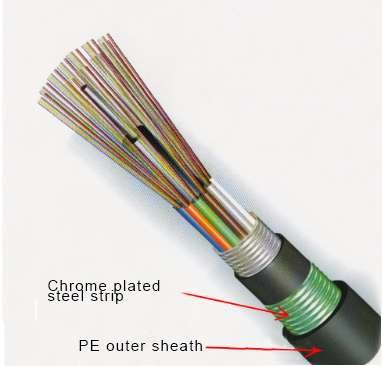
Directly buried cables generally adopt the GYTA53 structure, which is equivalent to adding chrome plated steel strips and polyethylene outer sheaths outside the protective layer of ordinary GYTA optical cables, as shown in Figure 2, thus giving the optical cable better protection performance.
In the 1990s, large-scale construction of long-distance (including current primary and secondary) optical cable lines began nationwide. At that time, long-distance cable lines were mainly laid by direct burial. The safety of directly buried cable lines is good, but the construction and maintenance costs are high and it is difficult to expand. Therefore, they are gradually being replaced by long-distance plastic pipeline air blowing and other laying methods. Currently, there are still a small number of constructions in some sparsely populated areas that are not suitable for overhead laying methods (such as grasslands and deserts).
From the perspective of project management, the construction content of burying long-distance plastic pipelines in the field is similar to that of burying optical cables directly. Therefore, some owners often manage long-distance plastic pipeline air blown optical cables as direct buried cable line projects, but from the perspective of cable laying methods, it should belong to pipeline cable laying.
2. Overhead laying
The overhead of optical cables refers to the suspension of optical cables in a space of 3.0 to 8.0 meters above the ground, supported by poles and other objects. The main support used for overhead cables is poles, and the distance between poles (the distance between adjacent poles) is generally around 50 meters.

The construction cost of overhead cables is relatively low, but their safety is also low. It is often easy to get hung up by ultra-high vehicles when crossing roads; When floods occur, it is common for connected roads to be washed away.

There are two main methods for overhead laying: using steel strand attachment and self-supporting overhead.
(1) Using steel strand attachment
The overhead aerial cable is mainly laid by attaching steel strands. This method requires first fixing the steel strands on the poles, and then attaching the cable to the steel strands through cable hooks, as shown in Figure 5. Usually, 1 to 4 steel strands can be fixed on each pole, and 1 to more optical cables can be attached to each steel strand.

Aerial cables generally adopt GYTS structure, with a layer of steel tape armor between the protective layer and the core of the cable (as shown in Figure 6), which gives the cable a certain ability to prevent bird pecking and rodent infestation.

(2) Self-supporting overhead structure
Self supporting overhead refers to a method of laying optical cables using a self-supporting optical cable with high tensile strength, which does not need to be attached by steel strands (as shown in Figure 7) and is directly fixed on supporting objects such as poles. Self supporting overhead is often used in scenarios where it is not convenient to lay steel strands, such as under power poles, in areas with strong air corrosion, or in sections where fiber optic cables do not need to be expanded for a long time after installation.

In scenarios along high-voltage power lines or where large-span installation is required, self-supporting cables typically use ADSS structure. The main load-bearing components of the optical cable are aramid yarn in the inner and outer protective layers, as shown in Figure 8.

In scenarios that require low-cost construction, self-supporting cables typically adopt figure 8 structure, with the main load-bearing component of the cable being the messenger wire in the cable, as shown in Figure 9.

3. Pipeline laying
The pipeline laying of optical cables usually refers to the cable installation in underground communication pipelines through traction or air blowing. Underground communication pipelines are generally composed of pipe groups buried underground and manholes at both ends of the pipe groups, as shown in Figure 10. A pipe group is usually composed of one or more plastic pipes. According to the different construction areas and section lengths, underground communication pipelines are usually divided into urban pipelines and long-distance pipelines.

Urban pipelines are usually built in densely populated areas such as urban areas, suburbs, or towns, with a length of about 100 meters. Optical cables are generally laid inside pipelines by manual traction (see Figure 11a) or mechanical traction (see Figure 11b).


Long distance pipelines are usually constructed in the wild, using 40mm/33mm silicon core plastic pipes with a section length of about 980 meters. The optical cable needs to be laid in the pipeline by blowing air, as shown in Figure 12a. Air blown cable laying is the process of blowing compressed air into a silicon core tube, causing the fiber optic cable to be suspended in the tube along with the high-speed airflow. At the same time, the cable blowing machine’s track conveyor mechanism clamps the fiber optic cable and transports it forward, as shown in Figure 12b.


In order to improve the utilization rate of pipe hole resources, micro pipes and micro cables have been widely used in communication pipelines along highways. The laying method of microtubes and micro cables can be found in the article “Isn’t air blown micro cables good when underground pipe hole resources are scarce?”
Other common laying methods for fiber optic cables
In addition to the three common laying methods of direct burial, pipeline, and overhead, in recent years, with the construction of high-speed railway lines, there have been more and more scenarios where optical cables are laid along high-speed railway channels. In addition, when directly buried lines (such as buried optical cables and buried silicon core pipelines) cross rivers, they involve underwater laying. When the optical cables enter the station, they also need to be laid inside the station. Due to space limitations, this article will not provide a detailed introduction to other methods of laying optical cables. Please see in article ”Main laying methods of communication cable part 2”.