 Skip to content
 In the design of broadband fiber optic access projects such as FTTH, the full attenuation of the ODN fiber optic link needs to be calculated based on the corresponding wavelength of the application system. On the one hand, it verifies whether the system’s optical power budget requirements are met, and on the other hand, it serves as a reference indicator for project acceptance.
Calculation method
The full attenuation of ODN fiber optic link refers to the attenuation between the S/R and R/S reference points in the fiber optic link from OLT to ONU. The common reference model for ODN fiber optic link attenuation is shown in Figure 1, which usually includes fiber and fixed connection attenuation Af, optical splitter insertion loss As, active connection insertion loss Ac, and additional loss Aa.

In the design, the calculation of ODN fiber link attenuation should adopt the worst-case value calculation method, that is, the relevant indicators should use technical indicators in standards, specifications or bidding documents, rather than actual typical indicators (average values of corresponding product indicators of first-line manufacturers). For example, in relevant standards, the attenuation index of active connections is 0.5dB/piece (any two connectors of the same model are interconnected), and the typical index of products from first-line manufacturers generally does not exceed 0.25dB/piece. When calculating, it should be taken as 0.5dB/piece.
Optical Fiber and fixed connection attenuation Af
Fiber optic and fixed connection attenuation Af includes fiber optic attenuation and fixed connection attenuation.
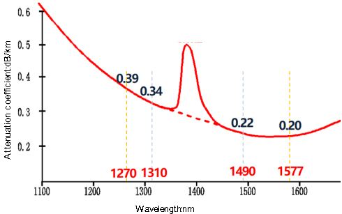
Fiber attenuation=Fiber attenuation coefficient (dB/km) x Fiber length (km). The attenuation coefficient of optical fibers is related to the wavelength used in the system. The typical values of the attenuation coefficient of optical fibers at the upstream and downstream wavelengths of GPON and XG-PON are shown in Figure 2.
Fixed connections are relative to movable connections, including mechanical joints (cold joints) and fusion joints. Mechanical termination is mainly used at the on-site termination of drop cables, as shown in Figure 3. The stability of on-site welding is poor, and with the popularity of portable fusion splicer, it has gradually been replaced by fusion termination methods.

The average attenuation index of fixed fiber optic connections is shown in Table 1.
| Splicing method | Attenuation (dB/piece) | |
| Single fiber | Ribbon fiber | |
| Fusion splicing | 0.06 | 0.12 |
| Cold splicing | 0.10 | – |
In ODN, it is often difficult to know how many fiber optic connectors are included in the entire fiber optic link, and the attenuation caused by fiber fusion splicing accounts for a very small proportion of the attenuation in the entire fiber optic link. Therefore, when calculating, the attenuation of the fiber optic and the attenuation caused by fusion splicing are often combined together to simplify the calculation. The reference values for attenuation per kilometer of optical fiber and fusion splicing are shown in Table 2. When there are both single core connectors and fiber ribbon connectors in the link, the average value of single core splicing and fiber ribbon splicing is taken.
| Wavelength (nm) | Fiber fusion splicing attenuation (dB) | |
| Single fiber splicing | Ribbon fiber splicing | |
| 1270 | 0.43 | 0.45 |
| 1310 | 0.38 | 0.40 |
| 1490 | 0.26 | 0.28 |
| 1550/1557 | 0.24 | 0.26 |
The attenuation Af of optical fibers and fixed connections can be calculated by multiplying the reference values in Table 2 by the length of the optical fiber link. When the link includes cold connections, the cold connection attenuation can be calculated separately at 0.1dB per connection.
Optical splitter insertion loss As
In ODN, equal ratio spectroscopy splitter is mainly used. According to the different connection methods, equal ratio splitters are mainly divided into three types: steel tube type (mini splitter), box module type (abs spiltter) and plug-in type (LGX splitter), as shown in Figure 4. Box type splitters are mainly used in optical cable junction boxes, while patch type splitters are mainly used in optical cable splitter boxes.

Mini Splitter

ABS Splitter

LGX Splitter
For every 1 level increase in the splitting ratio of the splitter, the insertion loss increases by approximately 3dB. For ftth splitters with the same splitting ratio, the insertion loss of plug-in type splitters is about 0.2dB greater than that of box type splitters, as shown in Table 3.
| Split ratio | Insertion loss (dB) | |
| Abs module | LGX module | |
| 1×2 | 4.2 | 4.4 |
| 1×4 | 7.8 | 8.0 |
| 1×8 | 10.9 | 11.1 |
| 1×16 | 13.9 | 14.1 |
| 1×32 | 17.2 | 17.4 |
| 1×64 | 20.9 | 21.2 |
But in scenarios such as FTTR, rural areas, and inside buildings, the application of unequal ratio splitting is also increasing. Figure 5 shows a reference model for the attenuation of an ODN fiber optic link with unequal ratio splitting in a certain building scenario.

The main models of unequal ratio optical splitters are 1×5 splitter and 1×9 splitter. 1×5 splitter includes 1 cascade port and 4 branch ports, while a 1×9 splitter includes 1 cascade port and 8 branch ports. The reference values for insertion loss of 1×5 and 1×9 splitters are shown in Table 4.
| PLC split ratio | Insertion loss (dB) | |
| Cascade port | Branch port | |
| 1×5 | 1.8 | 15.7 |
| 1×9 | 2.4 | 16.3 |
Activity Connection Insertion Loss Ac
In ODN fiber optic links, active connections are usually used at the ODF, backbone optical switches, and optical splitters. The insertion loss of active connections is calculated at 0.5dB per connection. The insertion loss of a brand new active connector generally does not exceed 0.25dB/piece, but with the increase of usage time, due to end face contamination and other reasons, the insertion loss will increase to a certain extent. Calculated at 0.5dB/piece, it will not produce too much excess link attenuation.
OLT, ONU, and ODN also use active connections, but this active connection is not included between the S/R and R/S reference points and does not belong to the ODN fiber optic link.
Usually, each optical splitter has 2 active connections to the fiber link. However, according to the testing principle of splitter insertion loss in YD 2000.1-2014, as shown in Figure 6, the insertion loss value of the optical splitter already includes the insertion loss of 1 active connection. Therefore, when calculating Ac, only 1 active connection is required for each splitter.

Additional losses Aa
In ODN, due to non-standard construction and installation, as well as the use of G.652 tail fibers for termination in the entrance section of optical cables, significant macro bending losses are often incurred in the ODN link (see the articles “The Influence of Insufficient Fiber Bending Radius on ODN Link Attenuation” and “What is the Difference in Bending Resistance Performance between Commonly Used G.657 and G.652 Fibers”). For example, the downlink attenuation test results of some household optical cables in a certain city are shown in Figure 7 (each point in the figure represents different users), where the average attenuation of XG-PON users is as high as 2.85dB, and the average attenuation of GPON users is also 1.98dB.

Although the additional macro bending losses are mainly caused by non-standard construction and non-standard installation and maintenance, it is difficult for operators to take effective measures to solve this problem. Therefore, the additional losses caused by macro bending losses in ODN will exist for a long time. The additional loss Aa can be determined by referring to Table 5.
| Central wavelength(nm) | Additional loss Aa (dB) |
| 1270 | 0 |
| 1310 | 0 |
| 1490 | 1.0 |
| 1577 | 2.0 |
The additional loss of ODN fiber optic link mainly occurs in the entrance section. When the ODN fiber optic link does not include the entrance section optical cable line, the additional loss should not be recorded.
Calculation Examples
According to the calculation method and relevant reference indicators described above, the full attenuation of the ODN fiber link can be calculated for the proportional splitting shown in Figure 1 and the unequal splitting shown in Figure 5. When the ODN link is 5.0km long and the total branching ratio is 1:64, the calculation of the full attenuation of the GPON downlink ODN link is shown in Table 6.
| Item | Calculation Method | Calculation Result (dB) | ||
| Balanced splitting | Unbalanced splitting | |||
| Af | 0.26dB/kmx5.0km | 1.3 | 1.2 | |
| As | balanced | 10.9+11.1 | 22.0 | |
| unbalanced | 4.2+2.4*2+16.3 | 25.3 | ||
| Ac | balanced | 0.5×6 | 3.0 | |
| unbalanced | 0.5×4 | 2 | ||
| Aa | 1.0 | 1.0 | ||
| Link attenuation throughout the entire process | 27.3 | 29.5 | ||
It should be noted that when using unequal ratio optical splitter, the insertion loss of the branch port of the unequal ratio splitter is greater than that of the equal ratio splitter with the same number of branches by more than 5.0dB. When calculating the ODN full link attenuation, the R/S point is usually taken at the ONU connected to the last stage of the unequal ratio splitter at the far end of the link.
Due to the worst-case scenario calculation method used for the attenuation of ODN fiber optic links, the calculated results are slightly larger than the measured values. During the completion test, if the measured attenuation value of the fiber optic link is greater than the calculated result, it should be judged as unqualified.