 Skip to content
 Excessive attenuation of fiber optic lines is a common fault in Cable TV networks, and a graded treatment strategy should be adopted based on specific causes. The following is a systematic solution:
Quick self inspection and basic processing (user can operate independently)
Clean the fiber optic connector
Wipe the fiber end face with a 95% alcohol swab to remove dust or oil stains (each pollution point can cause 0.5-2dB loss).
Attention: FC/APC and FC/UPC interfaces must not be mixed to avoid increased reflection loss due to end face angle mismatch.

Check the fiber bending status
Ensure that all bending radii are greater than 5cm (for household butterfly cables) or greater than 15cm (for backbone cables).
Remove the tightly tied ties and eliminate right angle bending (bending loss can reach 1-10dB).
Restart and Basic Testing
Turn off the optical modem (optical network unit) and restart it after 5 minutes, observe the light signal indicator light:
Green light always on: normal (-8~-25dBm)
Red light flashing: Attenuation>-27dBm needs to be reported for repair.

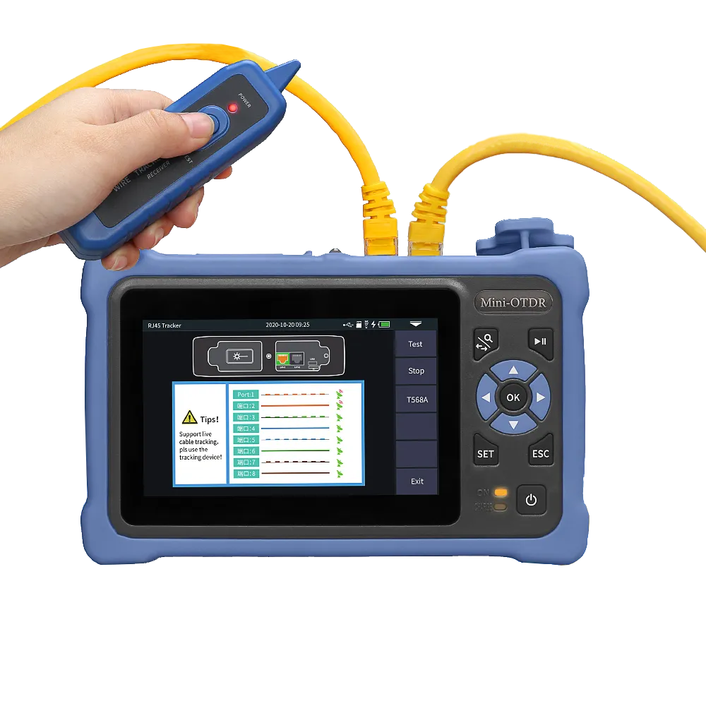
Professional level diagnosis and positioning
OTDR accurately locates the fault point
- Set 1550nm wavelength (sensitive to micro bending) and 10ns narrow pulse width (short distance high-resolution).
- Interpretation of Abnormal Curve:
- Breakpoint: sudden drop in curve (error ± 1m)
- High loss point: sudden slope change>0.5dB/km (indicating compression or poor quality welding).
Full process optical power verification
- Segmented testing using an optical power meter:
- Optical transmitter output: ≥+3ddB (1550nm)
- User end reception: -15~-20dBm (optimal for gigabit services).
Hierarchical solution
▶ Physical layer repair
| Fault Type | Handling plan | Expected consumption reduction |
| Joint contamination/damage | Re grind the end face or replace the LC/SC patch cord | 0.5~3dB |
| Micro bending/squeezing | Replace G.657A2 anti bending fiber (bending radius ≥ 7.5mm) | 1~8dB |
| Fiber optic cable aging | Replace the backbone optical cable (using low attenuation G.652. D fiber) | 0.2dB/km→0.17dB/km |
▶System level optimization
Replacement of splitter
- Melting cone type (FBT splitter) → planar waveguide type (PLC splitter), reducing additional losses (PLC loss 16dB vs FBT 19dB under 1:32 splitting).
- Add redundant split fiber links with isolation greater than 40dB to prevent single point failures.
▶Signal compensation
- Link distance>20km: Install EDFA amplifier (output 23dBm can extend transmission by 50km).
- 1550nm+1310nm hybrid service: using WDM multiplexer instead of traditional splitter.
Preventive maintenance standards
Regular testing
- Log in to the optical modem backend every month to record the light attenuation value. If the fluctuation exceeds 3dB, immediately investigate.
- Annual OTDR full link scanning to establish attenuation baseline.
Construction standards
- Melting point loss ≤ 0.08dB (hot melt)/≤ 0.3dB (cold melt).
- The insertion loss of the active connector is ≤ 0.5dB, and the radius of the tail fiber disc is greater than 8cm.
Key indicator reference:
- Critical value: Receiver > -25dBm (delayed packet loss)/< -9dBm (risk of optical module breakdown).
- Redundant design: Reserve 10% power margin throughout the entire process to cope with aging.
- Operations and maintenance require collaborative OTDR positioning and segmented power testing, with priority given to handling high loss physical nodes.