 Skip to content
 MTP® Connector is a high-performance MPO connector. MPO/MTP® Trunk cable meet both EIA/TIA-604-5 FOCIS 5 and IEC-61754-7 MPO fiber connector standards. Yingda pre-terminated able wiring solutions, that is, the termination and testing of optical wiring products are all completed in the factory, 100% tested and qualified before delivery. Yingda’s MPO/MTP® high-density pre terminated cable assembly is currently mainly used in three major areas: high-density environments in data centers, fiber-to-building applications, and connection inside optical transceiver equipment such as splitters, 40G, 100GSFP, SFP+, 400G QSFP-DD, 800G OSFP etc.
The line sequence type or polarity of MPO MTP trunk cable is described in the standard document ANSI/TIA-568-C.3 on various line sequence arrangements of MPO pre-terminated optical cables, MPO distribution boxes, and MPO couplers, as well as the interface form of 10/40/100/200G/400G/800G Ethernet multimode optical fiber transmission systems.
The following clearly summarizes the line sequence types A, B, and C of MPO fiber patch cords: Method A and Type A, Method B and Type B, Method C and Type C have the same meaning. Type A is parallel method, Type B is cross method, and Type C is line pair cross.
If an unprofessional fiber optic patch cord manufacturer or a manufacturer that only produces simplex and duplex patch cords but not MPO patch cords will not understand the concept well, they often confuse the parallel and cross methods of the MPO line sequence. To avoid confusion, it is better to refer to the drawings to reduce unnecessary losses.
Polarity types of MPO connectors
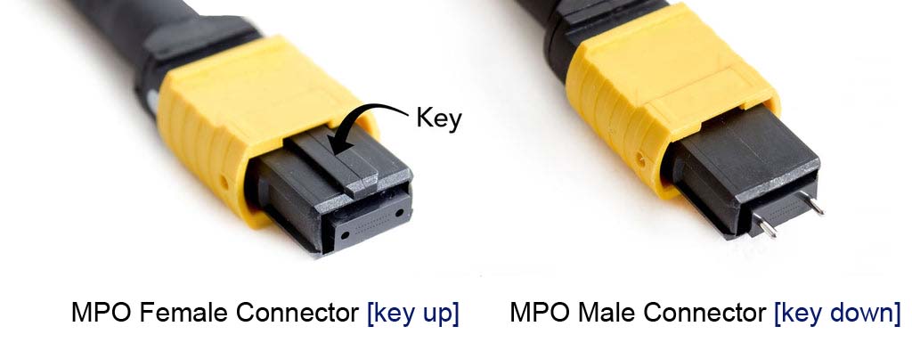
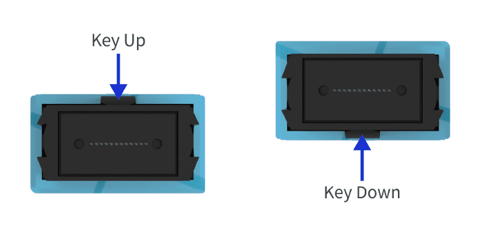
The polarity of MPO connectors is managed by the Alignment Key, which defines two types of Key: Key Up and Key Down.
Type A (parallel method):
The fiber cores at both ends of the patch cord are arranged in the same position, that is, 1 at one end corresponds to 1 at the other end, and 12 at one end corresponds to 12 at the other end. The key directions at both ends are opposite, key up corresponds to key down.

Type B (cross method):
The fiber core arrangement positions at both ends of the MPO jumper are opposite, that is, 1 at one end corresponds to 12 at the other end, and 12 at one end corresponds to 1 at the other end. The key directions at both ends are the same, that is, key up corresponds to key up, and key down corresponds to key down. In 40G QSFP modules, Type B is generally used, but which form is finally used needs to be confirmed with the customer.

Type C (line pair cross.):
Type C polarity means MPO patch cords have a pair of adjacent fiber cores that are crossed, i.e., fiber core 1 at one end corresponds to fiber core 2 at the other end, and fiber core 12 at one end is 11 at the other end. The key directions at both ends are also opposite, key up corresponds to key down.

Mating With Fiber MPO adapters
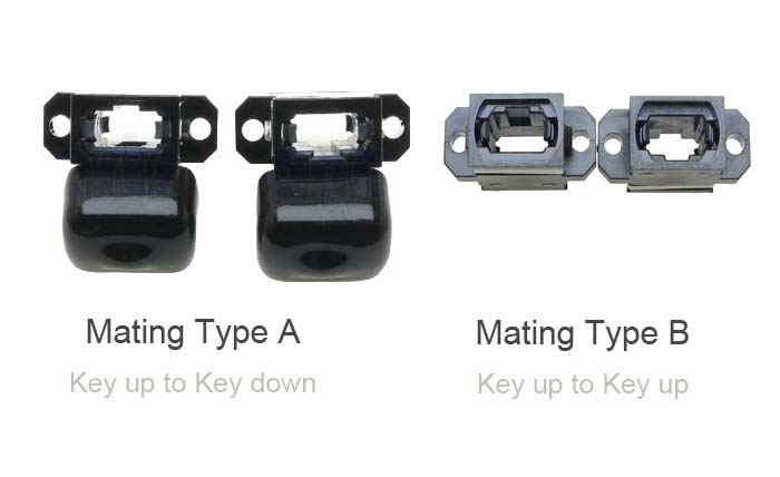
A pair of MPO connectors is mated with an MPO adapter. The MTP/MPO adapter uses an asymmetric shell with reverse keys to achieve correct fiber polarity. MPO adapters are available in two types: Type A (up-down, i.e. Key Up/Key Down) and Type B (up-up, i.e. Key Up/Key Up). MPO connectors (single mode) with an APC connection face have an 8° bevel and can only be mated with a Type A adapter.
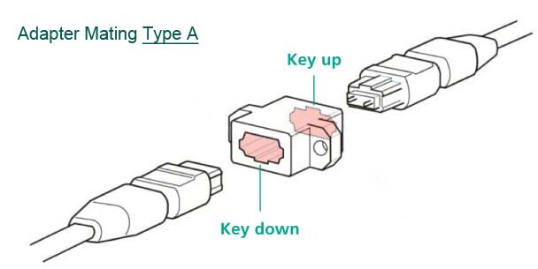
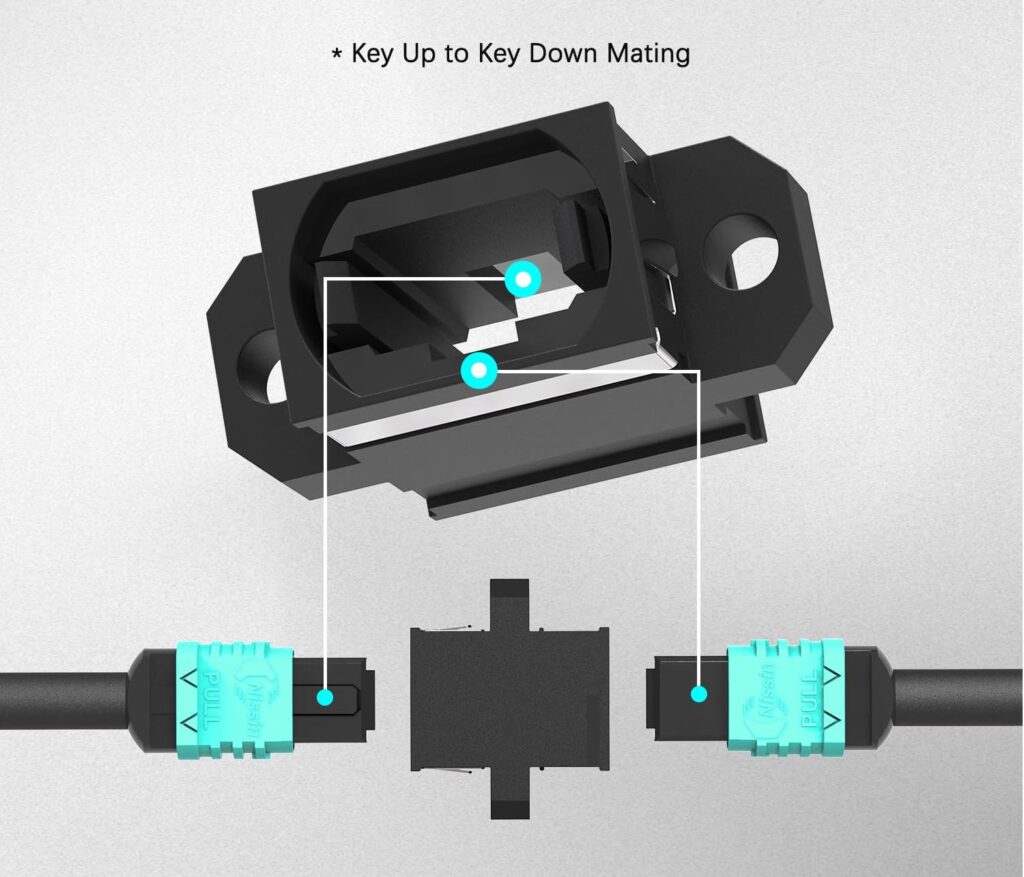
Mating type A MPO Adapter (key up to key down)
Mating type A MPO adapter’s keys are inverted to ensure that the fiber at position 1 is connected to position 1 in the MTP/MPO cable connector at the opposing end.
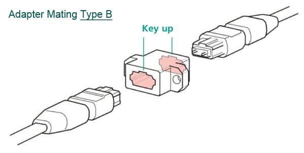
Mating type B MPO adapter (key up to key up)
Mating type B MPO adapter both keys are oriented facing up in order that both MTP/MPO cable connectors are mated “key up” wise. The fiber at position 1 is connected to position 12 in the MTP/MPO connector at the opposing end.
The connection between MPO connector and MPO adapter must follow certain principles:
1. The connectors must be connected with the same number of cores (such as 12 cores to 12 cores, 24 cores to 24 cores, etc.);
2. A MPO male connector and a mpo female connector are connected as a pair;
3. The connectors must be connected with the same polishing type (such as PC and PC, APC and APC).
FAQ
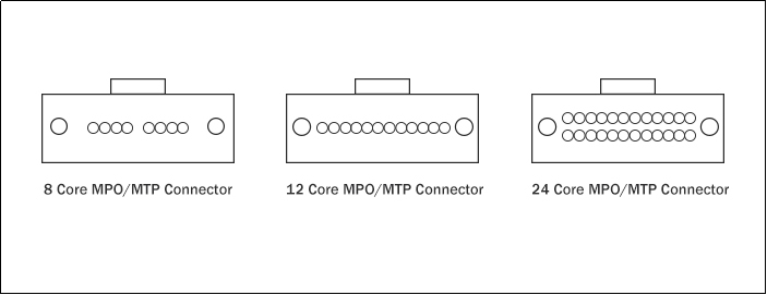
How many cores does an MPO connector usually have?
Currently, the factory-terminated components of MPO connectors can accommodate 6 to 144 fibers, among which 12, 16, 24 core MPO connector are more common. According to the IEC-61754-7 and EIA/TIA-604-5 (FOCIS 5) specifications, 12 core fibers are usually arranged in a row, which can support one or more rows of fibers in the same MPO connector. According to the number of cores arranged in the connector, it is divided into one row (12 cores) and multiple rows (24 cores or more).
40G MPO MPO patch cords generally use 12 core MPO multimode ferrules; 100G MPO to MPO patch cords generally use 24 core MPO ferrules.
There are currently 16 single row fiber array types on the market, which can be divided into multiple rows to form 32 cores or more. 16 core or 32 core MPO fiber connectors will become the best solution for low-latency and ultra-high-speed transmission of the next generation 400G, 800G network with AOC cable or DAC cable formation.
What are the differences in the application of MPO fiber jumpers with different cores?
According to Yingda many years of experience in optical transceivers and wiring, it is generally used for 40G, 100G QSFP SR4, QSFP28 SR4, and an 8 core MPO cable crossover can be selected, that is polarity type B. 24 Core MPO is generally used for wiring in computer rooms. In the past, there was a 10* 10G 100G multimode CXP-SR10 module, but this module is almost not used. Generally, 100G short distance transmission use 100G SR4 (100G-QSFP28-SR4).
How to determine the fiber sequence of the MPO multi-core connector?
Because MPO is a multi-core connector, in order to visually analyze the fiber sequence 1, 2,3 to 12 cores with the naked eye, there is a white dot design on the side of the connector. The end with the white dot is optical fiber 1, and the other end is fiber 12. If the fiber is arranged in 2 rows with 24 cores, the end with white dots is 1 and 13, and the other end is fiber 12 and 24, as shown in the figure below.
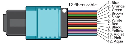
During the production process, when the ribbon fiber is inserted into the MT ferrule, since the bare fiber coating has color, it can be distinguished according to the international standard color of ANSI/TIA-598-D as 1, 2, … 12, because the colors of the ribbon fiber are as below table:
| 1 | 2 | 3 | 4 | 5 | 6 | 7 | 8 | 9 | 10 | 11 | 12 |
| Blue | Orange | Green | Brown | Slate | White | Red | Black | Yellow | Violet | Pink | Aqua |