Skip to content
 Optic fiber coupler is a passive device that distributes optical power based on fused biconical tapered fiber technology. It is manufactured by fusing and stretching multiple fibers, using a tapering process to monitor the splitting ratio in real time. This creates a single-input, multi-output splitting structure, with a splitting ratio that can be flexibly adjusted from 1:99 to 50:50. This fused fiber coupler uses 1×2 or 1×4 as the basic unit to achieve multi-channel coupling. The core materials include a quartz substrate, optical fibers, and stainless steel tubing. Its low insertion loss and rapid customization capabilities meet the needs of flexible deployment in various scenarios, but it should be noted that temperature stability limits its application in harsh environments.
Optic Fiber Coupler Technical Principles and Process
- Manufacturing Process: Strip the fiber caoting of the two or more optical fibers and bring them into close contact. Under high-temperature melting conditions, they are axially stretched to form a tapered coupling region. A specific splitting ratio is achieved by controlling the stretching speed and twisting angle.
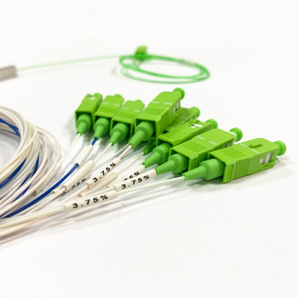
- Channel Expansion: Due to process limitations, a single tapering process can only produce OFC coupler with splitting raio less than 1×4. Higher channel counts require cascading multiple 1×2 units and integrating them into a single package.
Core Features and Advantages of Fused Coupler
| Features | Parameters/Description | Application Value |
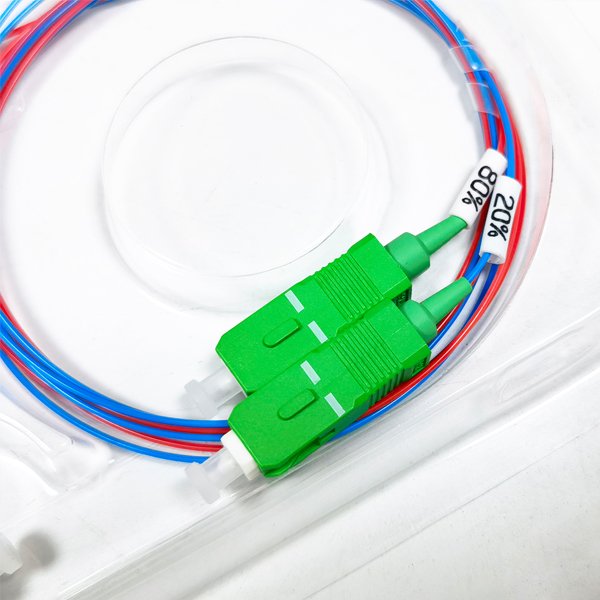
| Flexible splitting ratio | Any custom ratio between 1/99 and 50/50 (unbalanced splitter & balanced splitter) | Suitable for asymmetrical power distribution scenarios |
| Low insertion loss | ≤0.2dB (typical value for balanced splitter) | Reduces system optical power loss |
| Polarization-dependent loss | ≤0.1dB | Ensures signal transmission stability |
| Cost and development cycle | Low raw material cost, short development cycle | Highly cost-effective for small to medium-volume customization |
Optical Fiber Coupler Limitations
- Wavelength sensitivity: Loss fluctuates significantly with the input light wavelength, requiring strict matching of the operating wavelength (e.g. 1310/1550nm, etc.).
- Poor temperature stability: Temperature changes cause insertion loss drift, and the operating temperature range is typically -40℃ to +85℃.
- Channel expansion defects: When the number of channels is greater than 4, the device size increases and uniformity decreases.

10 90 Optical Coupler

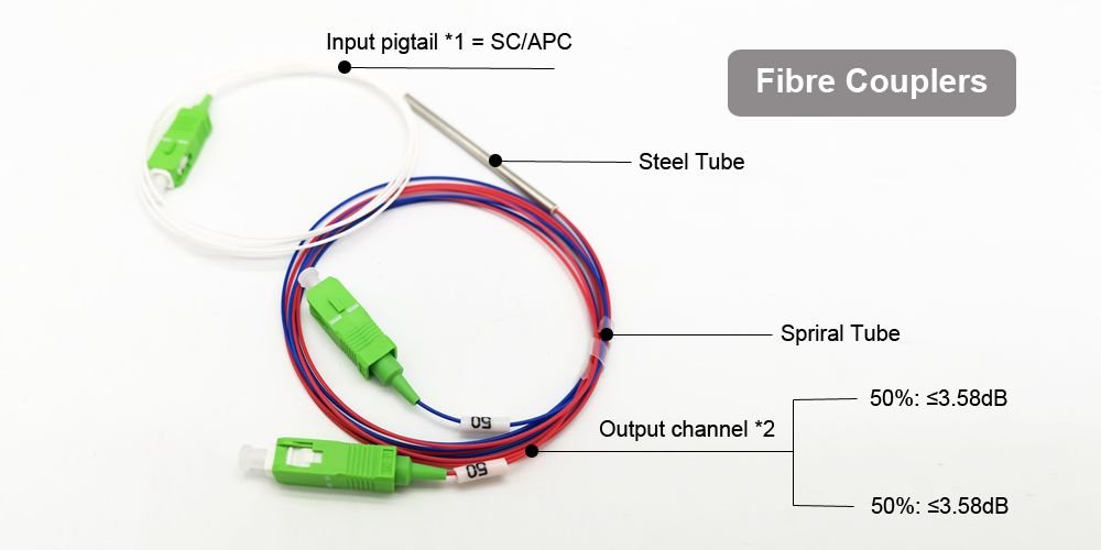
50 50 Fiber Coupler
Coupler Fiber Application
Fiber cable couplers are mainly used in optical fiber communication systems, CATV, FTTH, and fiber optic sensors.

Optical Fiber Communication Systems
As a basic optical power distribution component, tapered fiber couplers are widely used in MAN, WAN, and core optical network nodes to achieve flexible signal routing and branch transmission. Especially in early fiber optic cabling, such as low user density FTTX access layer and areas, low-cost splitting networks can be built by cascading 1×2 single mode coupler in a tree topology. At the same time, the low polarization-dependent loss characteristics of FBT coupler ensure the stability of short-distance signal distribution in small and medium-sized optical distribution networks.

Enterprise Networks and Local Area Networks (LAN)
FBT fiber couplers can be used for optical path splitting within data centers, enabling the sharing of optical signals between server clusters and supporting high-density connection requirements. Their customizable splitting ratio (balanced fiber splitting or 1/99 unbalanced calbe splitting) adapts to different business load scenarios.

Fiber Optic Device Integration
The fiber optic cable coupler acts as a pump combiner in erbium-doped fiber amplifier (EDFA) systems, combining multiple pump lasers to improve gain efficiency; it distributes output energy within fiber lasers, ensuring synchronous output across multiple channels.
Fiber Optic Sensing Networks
The optical coupler are suitable for distributed sensing systems, such as temperature and stress monitoring networks, enabling parallel signal acquisition from multiple probes through beam splitting. The splitting accuracy directly affects measurement accuracy. Tapered fiber couplers can also be used in optical instruments to achieve optical path power adjustment and monitoring.
Technology Selection Guide
| Scenario Requirements | Recommended Optical Splitter Types | Reasons |
| Splitting channel ≤ 4: Unbalanced splitter is required | Fused tapered fiber splitter | Flexible and customizable splitting ratio, low cost |
| Splitting channel ≥8: Wide temperature range operation is required. | PLC planar waveguide splitter | Strong channel expandability, high temperature stability |
Note: In the critical range of 1×4 to 1×8 splitting ratios, the selection should be made based on a comprehensive consideration of splitting ratio requirements and cost budget.