Skip to content
Description
Passive optical splitter for divided equally or converge optical signal. The design of planar waveguide technology provided a low-cost optical splitter solution with a small package and high reliability features.
Features of Splitter 1×32 in FTTH
- Low Insertion loss
- Low PDL
- Compact Design
- Good channel-to-channel uniformity
- High Reliability and Stability
- Conforms to Telcordia GR-1209&GR-1221, ROHS
Splitter 1×32 in FTTH Applications
- FTTX Systems
- PON Networks
- CATV Links
- Optical Signal Distribution
PLC Splitter 1×32 Technical Specification
| Parameters | 1×32 |
| Operating Wavelength(nm) | 1260~1650 |
| Insertion Loss (dB)(P/S Grade) | 16.5/ 16.9 |
| Loss Uniformity(dB) | 1.5 |
| Return Loss (dB)(P/S Grade) | 55/50 |
| Polarization Dependent Loss(dB) | 0.3 |
| Directivity (dB) | 55 |
| Wavelength Dependent Loss(dB) | 0.5 |
| Temperature Stability (-40~8℃)(dB) | 0.5 |
| Operating Temperature(℃) | -40~85 |
| Storage Temperature(℃) | -40~85 |
Note:
Specified without connectors.
Add an additional 0.15dB loss per connector
Detailed Display of Splitter 1×32 in FTTH
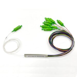
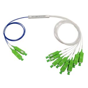
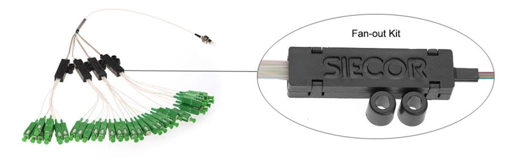
There is usually one input fiber port. In the following image, the single fiber with a connector (the FC connector shown) is the input side. This is where the incoming optical signal from the feeder fiber enters the splitter. There are 32 output fiber ports. The green-colored connectors are the output ports. These ports distribute the split optical signals to multiple subscriber lines in the FTTH network.

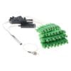
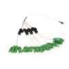
The 1×32 splitter in FTTH consists of a splitting module. In the following images, there is the black “SIECOR” marked components which are part of the splitter’s mechanical and functional structure. These components help in housing and protecting the internal optical splitting elements. It provides mechanical protection to the internal optical fibers and splitting elements, which is designed to withstand the rigors of installation, such as being placed in optical distribution boxes (ODBs) or other FTTH network elements. The structure helps in preventing fiber bending, which can cause signal loss.

Mini Module Steel Tube Size
| Part no. | Split ratio | Dimension/mm |
| YDPLC-MM-102 | 1X2 | 60*7*4 |
| YDPLC-MM-104 | 1X4 | 60*7*4 |
| YDPLC-MM-108 | 1X8 | 60*7*4 |
| YDPLC-MM-116 | 1X16 | 60*12*4 |
| YDPLC-MM-132 | 1X32 | 80*20*4 |
| YDPLC-MM-164 | 1X64 | 100*40*6 |
| YDPLC-MM-202 | 2X2 | 60*7*4 |
| YDPLC-MM-… | … | … |
Order information
| Port configuration | Input fiber type | Input fiber length | Output fiber type | Output fiber length | Input connector | Output connector |
| 101=1×2 | B=250um bare fiber | 10=1.0m | B=250um bare fiber | 10=1.0m | 00=None | 00=None |
| 104=1×4 | L=900um loose tube | 15=1.5m | R=ribbon fiber | 15=1.5m | FC=FC/UPC | FC=FC/UPC |
| … | T=900um tight tube | 20=2.0m | F=fan-out with 900um loose tube | 20=2.0m | FCA=FC/APC | FCA=FC/APC |
| 202=2×2 | … | … | … | … | ||
| … |