 Skip to content
 Yingda has over a decade of experience in professional fiber cable patch cord production, strictly adhering to international standards and ISO quality management system requirements. Our fiber optic cable patch cords undergo over a dozen production processes, with 100% monitoring and testing throughout the entire process. Only qualified products are shipped.
Fiber optic loss has many aspects. In addition to the loss of the fiber itself, we primarily inspect the insertion loss, return loss, and 3D end-face condition of the fiber connector. Once the fiber connector has been polished and the end-face is qualified, the connector is assembled and then subjected to these tests.
Below, we will explain the testing standards, testing equipment, testing methods, and precautions. Hope this will be helpful.
Yinda Standard Product Qualification Standards
| Test item | Telecom standard | Test instruments |
| Insertion loss | ≤0.3dB | Optical Power Meter, Insertion loss & Return Loss Meter |
| Return loss | ≥50dB(APC); ≥60dB(APC); ≥30dB(PC) | IL&RL tester, OFDR |
Fiber optic testing equipment maybe used
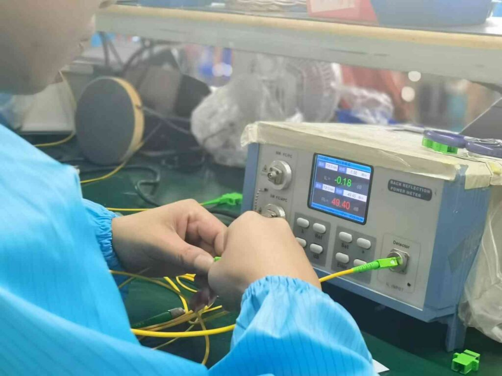
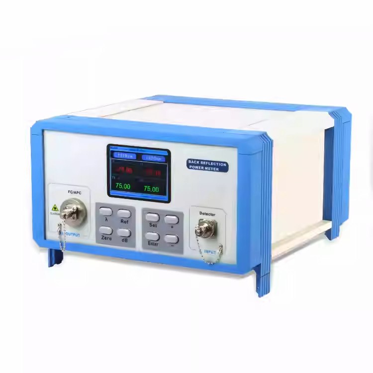
IL&RL tester
Insertion loss and return loss testerSuitable for single mode and multimode fiber cableThe highest and most accurate precision, and strong anti-interference ability.
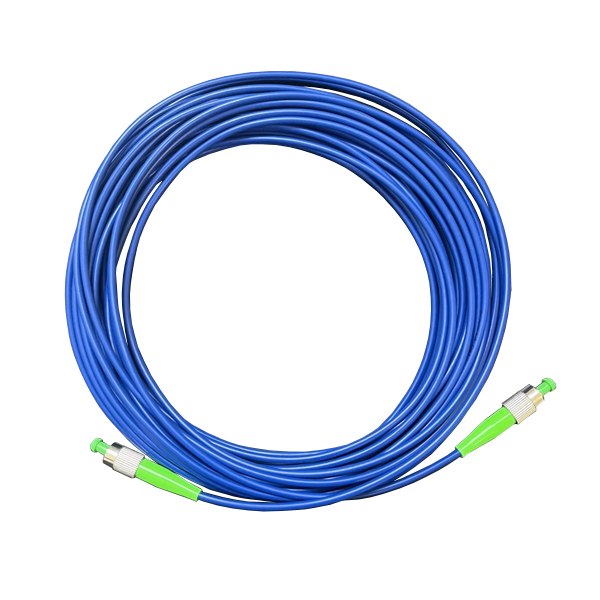
Master patch cord
As a reference fiber cable patch cord for testStandard types are FC to FC patch cord, FC SC patch cords, FC LC patch cord, and FC ST patch cords.High reuse times and good stability
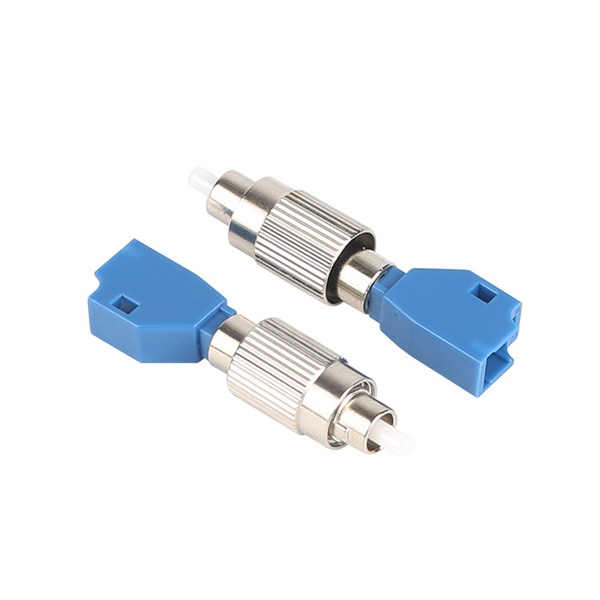
Master fiber adapter
Connect the master patch cord and the test patch cords. Commonly types are adapter SC, ST, FC, LC or hybrid adapters FC to LC, FC to ST, and FC to SC, etcHigh reuse times and good stability
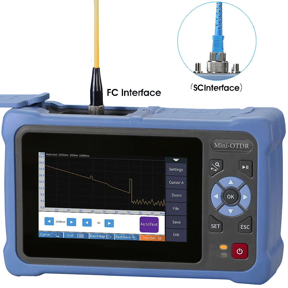
OTDR / Light Source
Mix VFL, power meter, light source, IL&RL tester in a setTransmits optical signals of specific wavelengths, single-mode 1310nm/1550nm, multi-mode: 850nm
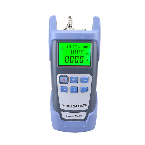
Optical Power Meter
Power meter wavelength must be consistent with the light source, with an accuracy of ≥0.03dB and a display resolution of ≥0.01dB
Fiber Optic Cleaning Kit
Ensure that the fiber end face is free of contamination with 2.5mm fiber cleaning pen for SC, ST, and FC, and a 1.25mm fiber cleaning pen for LC and MU, dust-free paper, alcohol cotton

Three test methods for fiber cable patch cord
Test Method 1: Single fiber jumper reference method (Common Method)
- Equipment Calibration
Connect master patch cord to light source and optical power meter. Turn on the light source and record the initial optical power value (P1). Set the optical power meter to dB and perform a zero reset (reference value calibration).
- Connect the fiber cable patch cord under test
Connect the master patch cord to the fiber cable patch cord under test via the master fiber adapter. Clean the end faces of other end of the fiber cable patch cord and then insert into the optical power meter. Read the current optical power value (P2). Insertion loss is calculated using the formula: IL = P2 – P1 (in dB).
- Compliance Verification
Telecom standard: Single patch cord insertion loss ≤ 0.3dB (1310/1550 wavelength). If the result exceeds the threshold, the patch cord fails.
Test Method 2: Insertion Loss & Return loss Tester
- Equipment Calibration: Connect the instrument with master patch cord and perform return loss (RL) and insertion loss (IL) calibration, ensuring RL values are ≥ 50dB.
- Patch Cord Test: Connect the patch cord under test via the master fiber adapter and read the insertion loss (IL) values at both ends. Wrap the cord around the test patch cord at least five times and measure the return loss (RL). Telecom requirements require RL ≥ 45dB.
- Result Analysis: Any port with insertion loss > 0.3dB or return loss < 45dB is considered unqualified.
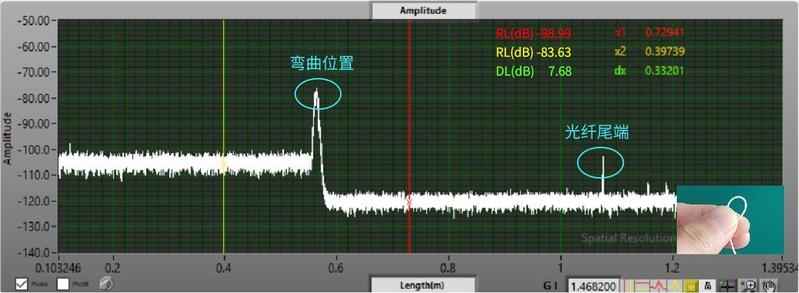
Test Method 3: Backscatter (OTDR/OFDR)
Using distributed fiber analysis technology, a single measurement of the entire link loss distribution allows for direct fault location.
- Insertion loss calculation: IL = (RL1 – RL2)/2 (RL1 and RL2 are the return loss values before and after the DUT).
Testing Precautions
- Wavelength Consistency: The wavelength of the light source and optical power meter must match.
- Endface Cleaning: Before testing, clean the endface in one direction with a dust-free tissue dipped in 99% alcohol. Do not wipe it back and forth; contamination can cause loss deviation >0.5dB.
- Environmental Interference: Avoid bending or stressing the fiber. Recalibrate the equipment if the temperature changes >1°C.
- Connection Stability: Ensure that LC/SC patch cords are locked with a click, and that FC patch cords are tightened.
Common faults and solutions
| Abnormal phenomena | Possible reasons | Solution |
| IL>0.8 dB | End face contamination or scratches | Clean or replace the fiber cable patch cord |
| The RL value is 10dB lower than the standard. | Connector loose | Reset and lock the patch cable |
| The OTDR curve shows a spike. | Fiber cable patch cord partially broken | Replace the fiber cable patch cord and check for any kinks in the patch cable. |
Test tool selection
| Scenario | Recommend tool kit | Application scenarios |
| Rapid acceptance inspection of computer rooms | Power meter + light source | Rapid machine room acceptance inspection |
| High-precision backbone network testing | OTDR | High-precision backbone network testing |
| Mass production quality inspection | 3D interferometer + return loss meter | Mass production quality inspection |
The above process can cover 99% of fiber cable patch cord loss testing needs. The key lies in equipment calibration, end-face control, and environmental stability.
Loss Test FAQ for Fiber Cable Patch Cord
Which testing method is most accurate?
An insertion loss and return loss tester is essential for telecom quality testing. Its dual-parameter calibration capabilities and anti-interference design ensure reliable results. In engineering and maintenance scenarios, an OTDR and IL&RL tester can be used together for both efficiency and accuracy.
What are the loss standards for fiber cable patch cords?
The fiber cable patch cord standard is IL < 0.3dB, return loss ≥ 50dB (APC); ≥ 60dB (APC); ≥ 30dB (PC).
How to determine if a fiber cable patch cord is qualified?
First, visually inspect the product to see if details match the order specifications, such as label, appearance, length, printing, color, and quantity. If so, then use a fiber optic tool to verify that the specific technical parameters comply with international standards and the specific requirements in the order. If they are within the standard range, the cable passes; otherwise, it fails.