 Skip to content
 In current GPON passive optical network solutions, 1X2 fiber splitter is a dispensable passive components, and its insertion loss is a crucial metric for calculating overall fiber link loss. However, each company’s manufacturing processes and loss characteristics vary. Yingda strictly adheres to TELCORDIA standards, ensuring all loss levels meet international standards and are shipped only after they meet the exact requirements of the purchase order.
How can we effectively reduce insertion loss during actual deployment?
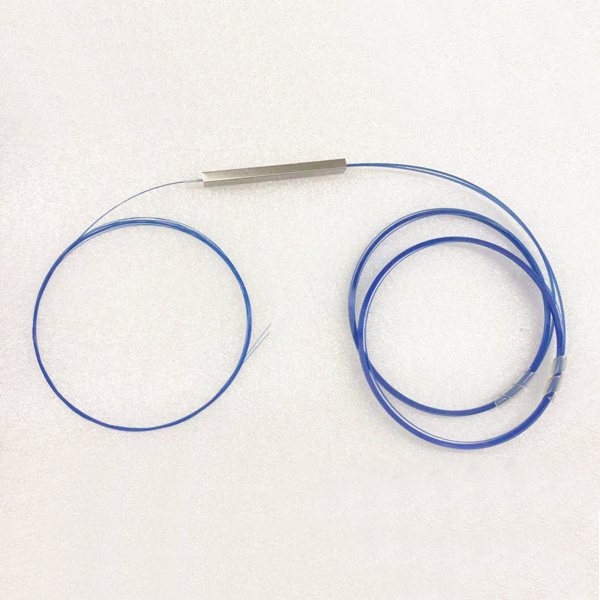
1×2 PLC Splitter Without Connector
If the 1X2 PLC splitter without connector, then a fusion splicer will be required before termination. In this condition, please pay attention to:
- When cut fiber, maintain an endface tilt angle of ≤0.5° to avoid refraction loss, each degree of deviation increases light signal loss by 0.2 dB.
- Then, wipe the optical connector endface ≥3 times with anhydrous ethanol and dust-free paper in a rotating pattern to eliminate scattering loss caused by dust.
- Finally, arc splice the fiber using arc fusion technology to ensure axial core misalignment ≤0.5 µm and splice point loss ≤0.08 dB. We recommend using a high-quality A-81S fusion splicer.
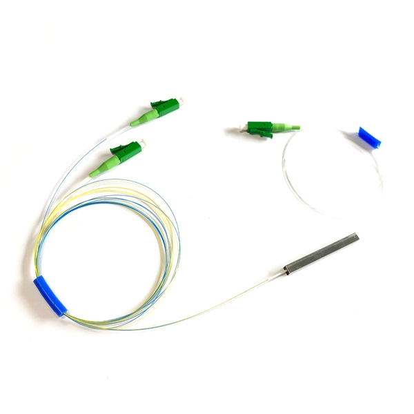
1×2 PLC Splitter With Connector
If a 1×2 fiber optic splitter comes with a fiber connector, you can directly insert into the adapter for termination. Preferred connectors include APC (beveled physical contact) connectors (return loss ≥ 60 dB) or UPC (ultra-precision connectors) with insertion loss ≤ 0.2 dB, which reduces return loss by 0.5 dB compared to PC connectors.
Generally, The splitters currently used on the market are single mode fiber splitters instead of multimode splitter. When inserting the active optical connectors, keep the axis perpendicular, with a tilt angle of less than 1°.
For multiple dynamic scenes, suggest to use PLC splitter instead of FBT coupler. For example, a 1×32 evenly split fiber optic cable with loss deviation of ≤0.8 dB, a 30% improvement over an FBT splitter.
Furthermore, using the same batch of fiber in the same optical fiber link, with mode field diameter variations of less than 0.5 µm, can avoid waveguide property mismatch and reduce inherent loss by 0.2-0.5 dB.
Other Ways To Reduce 1×2 Fiber Splitter Loss
- During the actual 1×2 fiber splitter wiring, for static cabling, maintain a bend radius ≥ 20 times the cable diameter (e.g., > 6 cm for Φ3mm cable). Use fiber guides during installation to avoid right-angle bends.
- For excess fiber, it is recommended to use a circular fiber tray with a diameter ≥ 8 cm. Use spacers between layers to prevent fiber compression. Also, leave ≥ 50 cm of fiber in the splice tray to eliminate thermal deformation stress.
- When the operating humidity is > 70%, activate a dehumidifier to prevent condensation and Fresnel reflection. When the temperature is < -10°C, use freeze-resistant packaging (such as a steel pipe splitter box).
- Use an OTDR (1310nm/1550nm dual-wavelength scanning) to monitor the entire splice process bidirectionally to ensure that both single-point loss and total link loss are within acceptable limits.
- Wear anti-static gloves throughout the entire process to avoid residue because of direct contacting with fiber end faces.
- Avoid using non-standard splitting ratios greater than 1:99 (for side-path loss greater than 21 dB). Instead, use a two-stage splitter cascade.
- Wavelength sensitivity: FBT splitters have 0.3 dB higher loss at 1550 nm than at 1310 nm. Multi-wavelength systems require pre-compensation.