 Skip to content
 The article “How to Calculate the Full Range Attenuation of ODN Fiber Optic Link” introduces the calculation method of the full range attenuation of ODN fiber optic link. The full attenuation A of the ODN fiber optic link should be less than the maximum channel insertion loss P allowed by PON, and a certain line maintenance margin M should be reserved, as shown in Equation 1.
P ≥A+ M (Equation 1)
The total attenuation A of the ODN fiber optic link is linearly related to the length of the fiber optic link. According to equation 1, the transmission limited distance L of the PON can be calculated.
Currently, GPON is evolving towards XG-PON, which commonly uses Combo optical modules. The following mainly introduces the calculation of transmission limited distance when XG-PON adopts Combo optical modules.
The maximum channel insertion loss P allowed by PON
The Combo optical module includes two channels: GPON and XG (S) PON (see “What is XGS-PON? How does XGS-PON coexist with GPON and XG-PON “. A total of four wavelengths, 1490nm/1310nm and 1577nm/1270nm, were used for the down/up direction. The maximum channel insertion loss P allowed for each wavelength is not the same, determined by the corresponding optical power parameters of the optical receiving/emitting components, which are “minimum average transmission optical power Ps” – “reception sensitivity S” – “maximum channel cost C”. The maximum channel insertion loss P allowed for Combo (Class C+) optical modules at different wavelengths is shown in Table 1.
| Parameter | Unit | GPON channel | XG-PON channel | ||
| Downlink | Uplink | Downlink | Uplink | ||
| Central wavelength | nm | 1490 | 1310 | 1577 | 1270 |
| Min. average transmitted optical power Ps | dBm | 3.0 | 0.5 | 5.0 | 2.0 |
| Receiving sensitivity S | dBm | -27.0 | -32.0 | -28.0 | -30.5 |
| Max. channel cost (20km) C | dB | 1.0 | 1.0 | 1.0 | 1.0 |
| Max. allowable channel insertion loss A1 | dB | 29.0 | 31.5 | 32.0 | 31.5 |
In the current network, GPON optical modem generally use Class B+optical modules, so the downstream receiving sensitivity of GPON channels in Table 1 is the value when the optical cat uses Glass B+optical modules. If the optical modem uses Glass C+optical modules (there are currently no related products on the network), the receiving sensitivity S is -30dBm, and the maximum allowable channel insertion loss P is 32.0dB.
It should be noted that due to the fact that the downstream of Combo optical module contains two wavelengths, 1490nm and 1577nm, when testing the downstream optical power of PON with a regular optical power meter in the ODN link, the test result is the sum of the optical power of the two wavelengths, which is about 3.0dB higher than that of a single wavelength. For example, the difference between the optical power values measured by a regular optical power meter and the network management values for some Combo (Class C+) ports is shown in Table 2.
| Manufacturer | Combo optical module unit | Power meter(dBm) | ||
| Network management value | Measured value | |||
| 1490nm | 1550nm | |||
| F | GPON | 4.88 | 7.88 | 7.91 |
| XG-PON | 6.02 | |||
| B | GPON | 5.12 | 8.85 | 8.83 |
| XG-PON | 5.72 | |||
Line maintenance margin M
In the appendix of YD/T 5206, the requirements for the value of maintenance margin in ODN are proposed, as shown in Table 3.
| Transmission distance km | Line management surplus value |
| L≤5 | ≥1 |
| 5<L≤10 | ≥2 |
| >10 | ≥3 |
However, due to the fact that the full attenuation A of the ODN fiber link is calculated using the worst-case value, it is usually 1.0dB to 2.0dB higher than the measured value; The maximum channel insertion loss P allowed by PON is also calculated based on the worst-case scenario, and the result is 1.0dB to 2.0dB lower than the actual performance of the device; Even if M takes a value of “0”, the system still has a maintenance margin of 2.0dB to 4.0dB; Therefore, the value of M should not be too large.
Standard appendices are generally used as technical references rather than technical requirements. And the fiber optic link length of ODN generally does not exceed 5.0km, with a maximum of 20.0km, and the line maintenance margin should be uniformly set at 1.0dB, after all, the line maintenance margin of long-distance line relay sections is generally only set at 3.0dB.


Calculation of Transmission Restricted Distance for XG-PON
Based on equation 1 and the composition of the full attenuation A of the ODN fiber link, equation 2 can be derived, which can be used to calculate the limited transmission distance L of xPON.
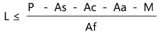
In the formula:
- As – Optical splitter insertion loss (dB)
- Ac – Active connection insertion loss (dB)
- Aa – Additional loss (dB)
- M – Line maintenance margin (dB)
- Af – Fiber and fusion attenuation per kilometer (dB/km)
The reference values for As, Ac, Aa, and Af can be found in the article “How to Calculate the Full Range Attenuation of ODN Fiber Optic Links”. Although the attenuation coefficient of the fiber at 1270nm wavelength is significantly higher than that of other working wavelengths of Combo, due to the different maximum channel insertion losses P allowed by Combo optical modules at different wavelengths, it is necessary to calculate the transmission limited distances at 1270nm, 1310nm, 1490nm, and 1577nm wavelengths separately, with the minimum value being the transmission limited distance of Combo.
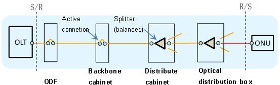
According to equation 2, the transmission limited distance of the ODN fiber link reference model (1:64 splitter) shown in Figure 1 at different operating wavelengths can be calculated, as shown in Table 4.
| Parameter | Unit | GPON channel | XG-PON channel | ||
| Downlink | Uplink | Downlink | Uplink | ||
| Central wavelength | nm | 1490 | 1310 | 1577 | 1270 |
| Maximum allowable channel insertion loss P | dB | 29.0 | 31.5 | 32.0 | 31.5 |
| Optical splitter insertion loss As | dB | 22.0 | 22.0 | 22.0 | 22.0 |
| Activity connection insertion loss Ac | dB | 3.0 | 3.0 | 3.0 | 3.0 |
| Additional loss Aa | dB | 1.0 | 2.0 | ||
| Link maintenance allowance M | dB | 1.0 | 1.0 | 1.0 | 1.0 |
| Fiber and fusion losses Af | dB/km | 0.26 | 0.38 | 0.24 | 0.43 |
| Restricted transmission distance L | Km | 7.7 | 14.5 | 16.7 | 12.8 |
From the calculation results in Table 4, it can be seen that the transmission limited distance of Combo optical module depends on the downlink of GPON channel. Generally, the transmission distance of XG-PON channel is greater than that of GPON. It can be seen that XG-PON using Combo optical modules can directly utilize existing ODN.
Conclusion
Due to the Combo optical module used in XG-PON, the transmission limited distance depends on the downlink of the GPON channel. Therefore, when calculating the transmission limited distance of the system, only the downlink transmission limited distance of the GPON channel needs to be calculated. The optical power index of the S/R reference point in the GPON channel of the Combo optical module is consistent with that of the GPON optical module (the optical power parameter of the GPON channel in the Combo optical module has an additional “maximum channel cost (20km)” term compared to the GPON optical module, which can generally be ignored). Therefore, the transmission limited distance when using the Combo optical module in XG-PON can still use the previous GPON calculation method and results.