 Skip to content
 The insertion loss calculation of the FO splitter needs to be combined with the splitting ratio and the additional loss. The specific method is as follows:
FO Splitter Calculation Formula
Insertion Loss (dB) = -10 x lg(splitting ratio) + Additional Loss
- Split Ratio: The ratio of power distribution at the output port (e.g., 50% corresponds to 0.5)
- Additional Loss: passive device intrinsic loss, typically 0.2dB ~ 0.4dB (depending on the manufacturing process)
Example Calculation:
Equal Splitting Scenario (1×2 FO Splitter, 50:50 Splitting)
- Theoretical Loss: -10 x lg(0.5) ≈ 3.01 dB
- Actual Loss: 3.01 + 0.3 = 3.31 dB (Additional Loss: 0.3 dB)

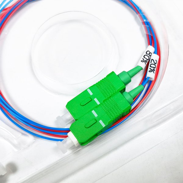
Unequal Splitting Scenario (1×2 FO Splitter, 20:80 Splitting)
- 20% End Loss: -10 x lg(0.2) + 0.3 ≈ 6.99 + 0.3 = 7.29 dB
- 80% End Loss: -10 x lg(0.8) + 0.3 ≈ 0.97 + 0.3 = 1.27 dB
Multi-Channel Equal Splitting (1×16 FO Splitter)
Single-Port Splitting Ratio = 1/16 = 0.0625
- Theoretical Loss: -10 x lg(0.0625) = 12.04 dB
- Actual loss: 12.04 + 0.3 ≈ 12.34 dB

Technical Data Acquisition Method
| Parameters | How to Obtain | Notes |
| Split ratio | Check the splitter’s data sheet or calculate using the following formula: Splitting Ratio = Port Output Power / Total Input Power | The splitting ratio of FBT splitters may fluctuate with wavelength. |
| Additional loss | Marked in the manufacturer’s technical documentation (usually 0.2–0.4 dB) | PLC splitters offer more stable additional loss. |
| Actual measurement | Using an optical power meter:Insertion Loss = Input Optical Power (dBm) – Output Optical Power (dBm) | Connector loss (approximately 0.5 dB/point) must be deducted. |
PLC Optical Splitter Key Considerations
- Wavelength Effect: Loss at 1550 nm is typically 0.1 ~ 0.3 dB higher than at 1310 nm (especially for FBT splitters).
- Uniformity Deviation: Loss deviation across all ports of a PLC splitter should be ≤0.8 dB; otherwise, the calculated value must be calibrated.
- Extreme Splitting Ratio: At a 1×2 1:99 splitting ratio, the secondary loss can reach as high as 21 dB (calculation: -10 x lg(0.01) + 0.3 ≈ 20.3 dB).

PLC Optical Splitter Measurement Verification Steps
- Input a stable light source into the splitter and record the input power, Pin;
- Use an optical power meter to measure the power, Pout, at each output port in sequence;
- Calculate the single-port insertion loss: IL = Pin – Pout, Unit: dB;
- Compare to the theoretical value. If the deviation is greater than 0.5 dB, check the connector or splitter quality.
Conclusion
In actual projects, the total fiber link loss needs to accumulate the PLC optical splitter loss, fiber attenuation (0.4 dB/km) and connector loss (fusion point ≈ 0.1 dB, connector ≈ 0.5 dB).