 Skip to content
 In the Cable TV network, the attenuation of fiber link requires comprehensive calculation of fiber transmission, splitter distribution, and connection point losses. The specific calculation steps are as follows:
Formula for Fiber Link Attenuation Composition
Total attenuation (dB)=fiber optic transmission loss + splitter loss + active connector loss + fusion point loss
Calculation basis for each sub item:
Fiber optic transmission loss
- Formula: Fiber optic cable attenuation coefficient (dB/km) x transmission distance (km)
Standard attenuation coefficient of single-mode fiber:
- 1310nm wavelength: ≈ 0.35dB/km
- 1550nm wavelength: ≈ 0.20dB/km
Fiber Optic splitter loss
- Theoretical formula: Insertion loss (IL)=-10lg (splitting ratio) (for example, when the splitting ratio is 1:16, IL=-10lg (1/16) ≈12.04dB)
- Engineering experience formula: Loss=n x 3+1 (n is the power of 2 of the denominator of the splitting ratio, for example, 16=2 ⁴in 1:16, n=4, Loss=4 x 3+1=13dB).
- Actual losses need to be added with additional losses (average 13.5dB for PLC type 1:16 spectrometers).
Loss of activity connector
- Each activity connection point (such as FC/SC/LC interface) has a loss of ≤ 0.5dB.

Splicing point loss
- Each fusion point loss is≤ 0.08dB (single-mode fiber).
Selection and loss control of splitters
| Split ratio | Theoretical loss (dB) | Empirical loss (dB) | Actual application range |
| 1:2 | 3.0 | 1.4 | Short distance branch |
| 1:8 | 9.03 | 10 | Community level allocation |
| 1:16 | 12.04 | 13~13.5 | Administrative village coverage |
| 1:32 | 15.05 | 16~17.5 | Metropolitan area node |
Selection principle:
For short distance distribution, choose the fusion cone type (FBT Splitter), and for long distance high-density distribution, choose the planar waveguide type (PLC Splitter);
The total attenuation throughout the process should be controlled within -15~-20dBm (the optimal range for optical receivers).


Attenuation acceptance and fault location
Acceptance criteria
- Full attenuation ≤ design value, with a 10% margin reserved to cope with aging;
- At a wavelength of 1550nm, the received power for gigabit services needs to be between -15dBm and -20dBm.
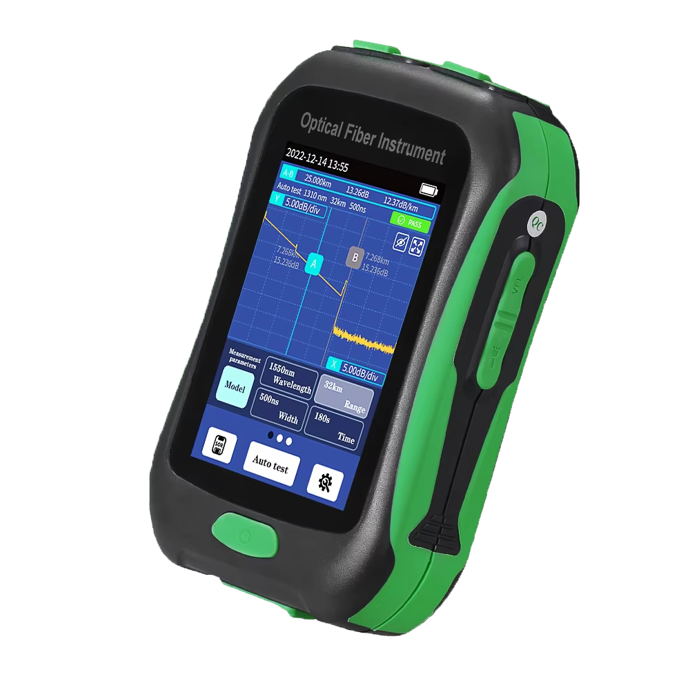
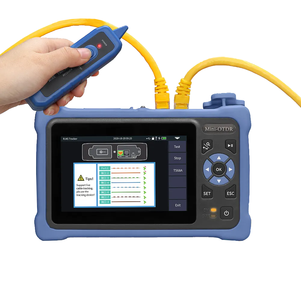
OTDR fault location
- Set the wavelength to 1550nm (sensitive to bending), and select the pulse width based on distance (long pulse width for 10km);
Abnormal judgment:
- Curve sudden drop → breakpoint (accuracy ± 1m);
- Minor decrease → Welding point loss>0.1dB needs to be optimized.
Design Case (10km Fiber Link)
Fiber link structure: Optical transmitter → 1:8 splitter → 2 active connectors → 3 fusion points → Optical receiver
Attenuation calculation:
- Fiber optic transmission: 0.20dB/km × 10km=2dB
- Optical splitter: 10dB (1:8 empirical value)
- Activity connector: 0.5dB × 2=1dB
- Fusion point: 0.08dB × 3 ≈ 0.24dB
- Total attenuation ≈ 2+10+1+0.24=13.24dB
→ Meet the receiving requirements of -15~-20dBm.
Key Reminder:
Deviation in the splitting ratio can cause fluctuations in the received power at the remote end. It is recommended to prioritize using a splitter with an additional loss of ≤ 0.2dB; It is recommended to use PLC splitter+OTDR bidirectional testing calibration for new network construction.