 Skip to content
 In the optical network topology, the emergence of fiber optic splitter helps users maximize network performance. An optical splitter fiber is a passive optical device that can decompose optical signals into multiple optical signal outputs, including one or two input ports and multiple output ports. When the optical network system needs to couple and distribute optical signals, an plc optical splitter can be used to achieve this. This article contains the following:
- Working principle of fiber optic splitter
- plc splitter optical attenuation and calculation method
- Optical fiber splitter self-loss measurement
What is an fiber optic splitter?
Fiber Optic Splitter also called fiber optic PLC splitter, is an integrated waveguide optical power distribution device that splits optical signals. For example, a 1×8 optical splitter can divide one input optical signal into eight output optical signals in equal proportions and transmit them in eight different channels. Today, optical passive splitters are widely used in passive optical networks (such as EPON, GPON, BPON, FTTX, FTTH, etc.) and play an important role.

Working principle of fiber cable splitter
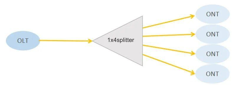
When the optical signal is transmitted in a single mode fiber, the optical energy cannot be completely concentrated in the fiber core for propagation, and a small amount of optical energy is propagated near the fiber cladding. In general, when the distance between the cores of two fibers is close enough, the optical signal transmitted in one fiber can enter the other fiber, that is, the optical signal can be redistributed between the two fibers, which is the origin of the optical splitter.

For example, a 1×4 optical splitter can distribute the optical signal in one fiber to four fibers in equal proportions. In fact, in simple terms, it is to evenly distribute 1000Mbps bandwidth to four households, and each household can use a network with 250Mbps bandwidth.
What is an acceptable DB loss for fiber splitter? How to calculate it?

- Optical power loss is related to the number of optical branches (each 1:2 split produces a loss of about 3.5dB)
- The optical power loss determines the transmission distance
- Bandwidth vs. cost: The average available bandwidth per household depends on the size of the split ratio. The larger the split ratio, the lower the OLT cost per household.
| Parameters | 1×2 | 2×2 | 1×4 | 2×4 | 1×8 | 2×8 | 1×16 | 2×16 | 1×32 | 2×32 | 1×64 | 2×64 | 1×128 | |
| Operating Wavelength (nm) | 1260~1650 | |||||||||||||
| Insertion Loss (dB)(P/S Grade) | 3.8/ 4.0 | 4.0/ 4.2 | 7.1/ 7.3 | 7.6/ 7.8 | 10.2/10.5 | 11.0/11.2 | 13.5/ 13.7 | 14.4/ 14.6 | 16.5/ 16.9 | 17.5/ 17.9 | 20.5/ 21.0 | 21.0/ 21.5 | 24.2/ 24.5 | |
| Loss Uniformity (dB) | 0.4 | 0.6 | 0.6 | 1.0 | 0.8 | 1.2 | 1.2 | 1.5 | 1.5 | 2.0 | 2.0 | 2.2 | 2.5 | |
| Return Loss (dB) (P/S Grade) | 55/50 | |||||||||||||
| Polarization Dependent Loss (dB) | 0.2 | 0.2 | 0.2 | 0.2 | 0.2 | 0.3 | 0.25 | 0.3 | 0.3 | 0.4 | 0.35 | 0.4 | 0.5 | |
| Directivity (dB) | 55 | |||||||||||||
| Wavelength Dependent Loss (dB) | 0.3 | 0.3 | 0.3 | 0.4 | 0.3 | 0.5 | 0.5 | 0.5 | 0.5 | 0.5 | 0.5 | 0.5 | 0.5 | |
| Temperature Stability (-40~85℃) (dB) | 0.4 | 0.4 | 0.4 | 0.4 | 0.4 | 0.4 | 0.5 | 0.5 | 0.5 | 0.5 | 0.5 | 0.5 | 0.5 | |
| Operating Temperature (℃) | -40~85 | |||||||||||||
| Storage Temperature (℃) | -40~85 | |||||||||||||
From the table above, we can see that many parameters show different attenuation values. We focus on wavelength, insertion loss, additional loss and splitting ratio. The most important performance indicator of the optical splitter is the different optical attenuation produced by the optical splitter under a specific splitting ratio. Under different splitting ratios, the optical attenuation of the splitter will also be different.
Except the return loss, all the loss are smaller, the better, such as Insertion loss, Polarization dependent loss, wavelength dependent loss, and temperature stability. Yingda will provide a test report for every one of the finished products with connector or without connectors when delivery, which ensure traceability if there is any problem.

The above part of the test report is the basic structure of the plc splitter, including fiber type, length, connector and types, fiber length and diameters, color, serial number, pack type and size. The below part show the test value of each port. As long as the test value is within our specification range, it is qualified.
Therefore, please confirm all details with sales team about the specific parameter requirements you need before placing an order every time to avoid mistakes, not only focus on price.
GET IN TOUCH
Custom Fiber Optic Splitter
How to calculate the fiber loss of plc splitter?
Fiber loss = transmitted optical power + additional loss + insertion loss + bare fiber loss
1. Calculation of split ratio
Formula: ki=Pi/SP*100%
Pi is the required driving power of each optical link, SP is the sum of the required driving powers of each optical link carried by the laser.
Note: In actual use, the manufacturer has indicated the splitting ratio, such as 80%:20% or 70%:30% for 1×2; 70%:15%:15% for 1×3; 70%:10%:10%:10% for 1×4.
2. Calculation of additional loss
In the actual operation process, the additional loss value can be measured. It is only necessary to detect and record the values according to certain operating specifications, and classify different links.
Generally, the loss of 1xN single mode splitter is as follows:
| Split ratio | 2 | 3 | 4 | 5 | 6 | 7 | 8 | 9 | 10 | 11 | 12 | 16 |
| Additional loss(dB) | 0.2 | 0.3 | 0.4 | 0.45 | 0.5 | 0.55 | 0.6 | 0.7 | 0.8 | 0.8 | 1.0 | 1.2 |
3. Insertion loss calculation
Formula: IL = -10lg (Po/Pi)
Where Po is the optical power at the output end, and Pi is the optical power at the input end.
Note: In the formula, Po/Pi is equivalent to the splitting ratio of the splitter, that is: IL = -10lg (ki).
For example, there is a 1×2 splitter, the splitting ratio is 20%:80%. The theoretical insertion loss of its 20% split link is -10lg (20%), which is approximately equal to 6.99dB.
4. Bare fiber loss calculation
Fiber loss generally decreases as the wavelength increases. In real, this value does not need to be calculated, and there is a certain reference standard. Strictly refer to the numerical standard, measure the loss values of different wavelengths, and determine the final loss value.
| Wavelength | Optical fiber attenuation coefficient (reference value) |
| 1310nm | 0.3~0.4dB/km |
| 1550nm | 0.15~0.25dB/km |
| 850nm | 3.75dB/km |
Note: Connector loss: generally 0.5dB each.
How to measure the loss of an optical splitter?
First of all, when an optical signal is transmitted through an ofc splitter, its loss value has nothing to do with the transmission direction. Whether the optical signal is transmitted from the input end of the optical splitter to the output end, or from the output end to the input end, the loss value is the same in both transmission directions. Therefore, we only need to measure the loss value of the optical splitter in one direction.

Now we take plc splitter 1×2 as an example to measure the loss in the downstream direction of the optical splitter, as shown in the figure below.
First, use a test fiber patch cable to connect the light source and power meter, set the reference value, and then use the test fiber patch cable to connect the light source to the input end of the splitter and the power meter to the output end of the 1×2 splitter, measure the loss value of the first output port, and then use the same method to measure the loss value of the second output port. Finally, the loss of the plc splitter can be obtained through the calculation formula.

Similarly, the above method can also be used to measure the loss in the upstream direction of the plc splitter. The difference is that the light source is connected to the output port of the plc fiber splitter, and the power meter is connected to the input port, as shown in the figure below.

For other 1xN optical fiber splitters, such as fiber optic splitter 1×32, the above measurement method can also be used. We only need to set the light source at the input port of the optical splitter, and then use the power meter and test fiber jumper to measure the loss of each output port in turn.
In addition, the above method is also applicable to the loss measurement of 2X2 splitters.
First, measure the loss value from one input port to two output ports respectively, and then measure the loss value from another input port to two output ports respectively. Similarly, this method can also be used to measure the loss of 2xN splitters, but the measurement process is more complicated and more values need to be recorded.
Note:
Due to the additional loss and connector loss generated during the production process of the fiber splitter, this measurement result will be slightly different from the actual optical splitter loss value.
How to Ensure a High Quality PLC Splitter?
In order to provide high-quality, stable, reliable and durable PLC splitters for FTTH projects, we have taken the following measures to ensure our quality.
- The chips and wafers of all our splitter products are from PPI in South Korea, with mature chip technology and good stability. At the same time, the ceramic ferrules of connectors are supplied from the top 1 company, with good concentricity and guaranteed stability.
- The production line workers are skilled in operation, especially the key steps such as fiber coupling are all skilled employees with more than 5 years of work experience;
- The glue for fiber tube splitter coupling, curing and UV is imported from the United States, and the optical fiber is fixed accurately, firmly and stably;
- Strictly follow the production process requirements, ISO quality management system, Telcordia GR-CORE-1209 and GR-CORE-1221 standard, and never omit or reduce the process to save time;
- All components and finished products will be tested for high and low temperature cycles to make the product more stable, with a temperature range of -40~+85°C to ensure the stable performance of the splitter under high and low temperature environments.

For more details about yingda’s quality control, please refer to quality management and lean manufacturing.