Skip to content
 At present, the phenomenon of ONU ONT low light is very common. Nationally, ONU low light accounts for 30%, that is, out of 100 users, the ONUs of 30 users have low light. We summarized the low light situation in a certain province, as shown in the figure below. Although after 2 years of debugging and rectification, there was still a low light rate of 4.59% in the end, with no major improvement.
| City | Low light rate (%) |
| xx1 | 6.75 |
| xx2 | 4.38 |
| Xx3 | 3.82 |
| Xx4 | 4.22 |
| Xx5 | 3.94 |
| Xx6 | 3.88 |
| Xx7 | 4.88 |
| Xx8 | 4.03 |
| Xx9 | 4.25 |
| XX10 | 4.78 |
| Xx11 | 4.59 |
What is ONU low light?
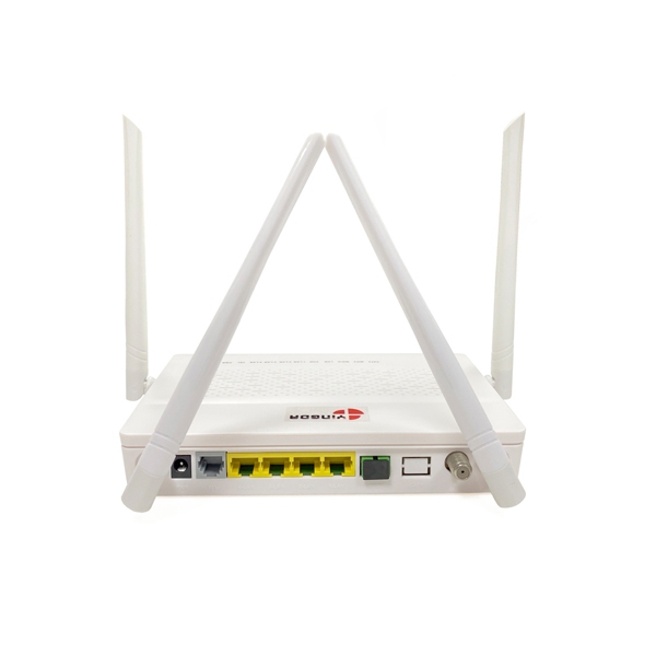
ONU weak light refers to the phenomenon that the optical power received by the ONU is lower than -27dBm, and -27dBm is the receiving sensitivity of the ONU. ONU weak light can cause slow network speeds, network lags, frequent disconnections and other network faults, which account for a high proportion and are difficult to rectify. Read more“The impact of ONU weak light on network speed”
Causes of weak light in ONU
Theoretically there are 2 aspects:
1. The optical power of the optical module (optical transceivers) of the central office equipment is insufficient;
2. The fiber link loss on the ODN optical distribution network from the central office to the user is too large.
However, after on-site testing, it was found that the optical power of all PON ports met the requirements. No excessive losses. Because we know that the standard transmit optical power range of GPON’s Class C+ optical module is +3dBm~+7dBm; The luminous power of the optical module corresponding to the PON port of the tested low-light ONU is: +4.0dBm~+5.5dBm, all of which meet the standard requirements.
Therefore, we determined that ONU weak light was caused by excessive ODN link attenuation.
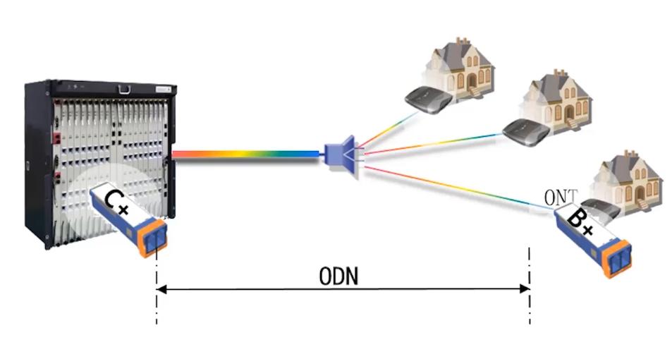
What are the ODN link losses?
According to experience and project test results, there are three main reasons:
Optical splitter loss, active connection loss, optical fiber and splice loss
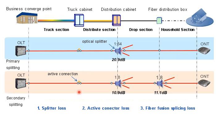
1. Attenuation of the splitter: After testing, it was found that the loss of all fiber optic splitters is lower than the standard value, so this reason is ruled out.
2. Loss of active connectors: After testing, it was found that 30% of active connectors had a loss exceeding 0.5dB, with a maximum of 1.0dB and an average loss of 0.36dB/piece; According to engineering standards, as long as the insertion loss of the active connector does not exceed 0.5dB, it meets the standard, so this reason has also been ruled out.
3. Loss of optical fiber and fusion splicing: Due to the attenuation of fiber optic fusion splicing is related to the fiber optic cable length, we have summarized our testing and found that: The average length of fiber optic links does not exceed 5km, and is generally within 10km. Only 1.02% of the distance exceeds 10km, so weak light has little to do with the length of the link. The weak light in ONU is not caused by an excessively long fiber link.
| Fiber link length(km) | Ratio(%) |
| 0~2 | 8.12 |
| 2~4 | 31.47 |
| 4~6 | 28.43 |
| 6~8 | 26.90 |
| 8~10 | 4.06 |
| ≥10 | 1.02 |
ODN link uplink and downlink attenuation
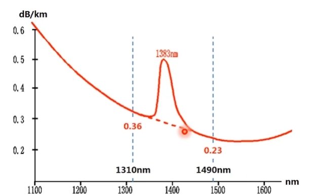
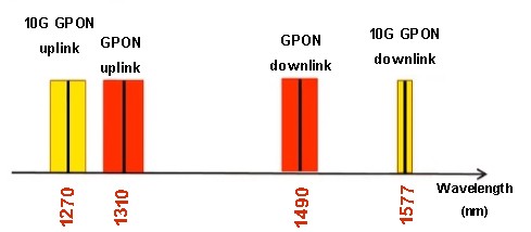
In the standard GPON scheme, the maximum downstream loss of OLT end Class C+ is 30dB, and the upstream loss is 32.5dB. The downstream wavelength is 1490nm and the downstream wavelength is 1310nm, according to the characteristics of light, the downstream attenuation of the ODN link should be about 0.36-0.23=0.13 (dB/km) lower than the upstream attenuation.
| Optical Transceiver Model | Min. transmission optical power(dBm) | Acceptance sensitivity(dBm) | Allowable max. channel insertion loss(dB) | |||
| OLT: Class C+ | OLT | 3 | OLT | -27 | downstream | 30 |
| ONU: Class B+ | ONU | 0.5 | ONU | -32 | upstream | 32.5 |
However, in our actual testing, the attenuation of the low light ONU is shown in the following figure:
| ODN optical link | optical link length (meter) | ONU power meter received (dBm) | Downstream loss (dB) | Upstream loss (dB) | Downstream additional loss (dB) |
| 1 | 4212 | -29.58 | 34.3 | 29.35 | 5.50 |
| 2 | 7500 | -30 | 34.45 | 27.5 | 7.93 |
| 3 | 2394 | -28.53 | 32.89 | 25.52 | 7.68 |
| 4 | 2394 | -27.7 | 32.06 | 23.85 | 8.52 |
| 5 | 1919 | -27.69 | 32.1 | 27.51 | 4.84 |
| 6 | 1881 | -30.45 | 34.86 | 24.89 | 10.21 |
| 7 | 1932 | -27.44 | 32.42 | 31.21 | 1.46 |
| 8 | 5065 | -28.86 | 33.89 | 29.32 | 5.23 |
| 9 | 3889 | -30 | 35.16 | 29.97 | 5.70 |
| 10 | 4405 | -27.44 | 32.64 | 27.65 | 5.56 |
| 11 | 2187 | -32.21 | 35.39 | 27.91 | 7.76 |
| 12 | 1711 | -27.69 | 30.89 | 22.12 | 8.99 |
| 13 | 1824 | -27.44 | 30.64 | 25.92 | 4.96 |
| 14 | 1546 | -29.2 | 32.4 | 29.75 | 2.85 |
Note: The excessive value of downlink loss (dB)=downlink loss (dB) - uplink loss (dB)+link length (km) * 0.13dB/km
The uplink loss did not exceed the standard (>32.5dB), and over 95% of the downlink attenuation exceeded the uplink attenuation, with an average attenuation of 5.47dB higher than the normal value for each link.
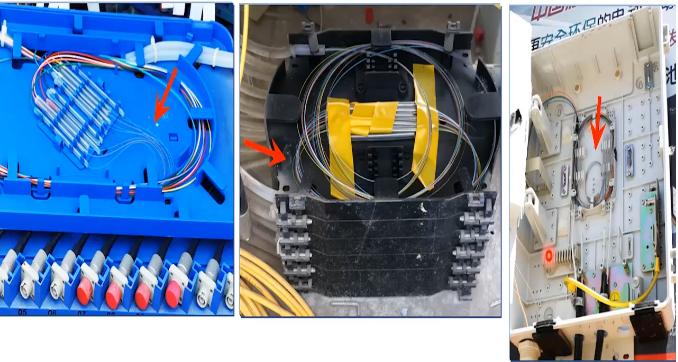
What cause the excessive loss of the downlink?
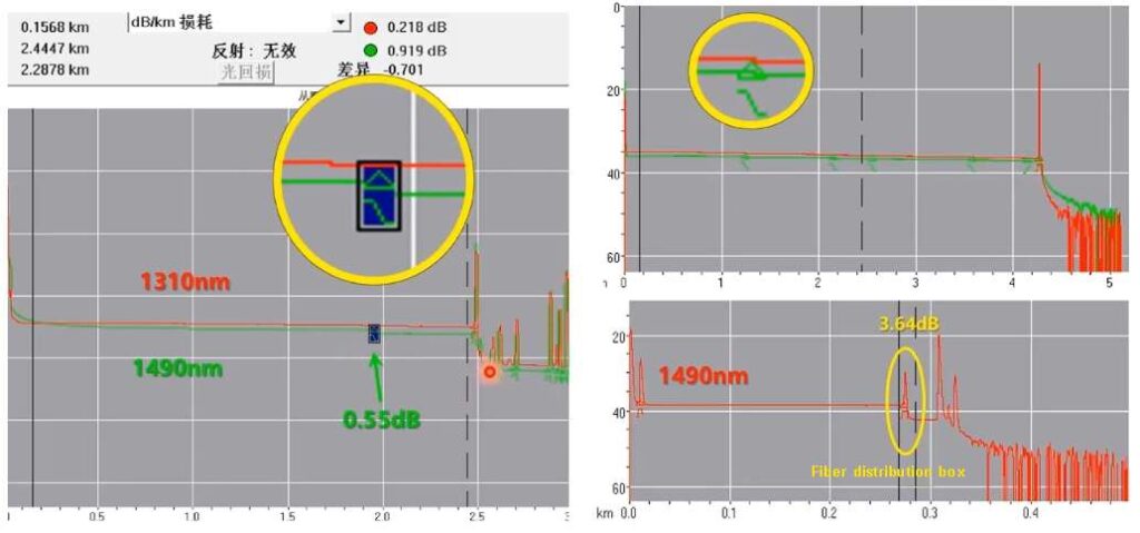
After final testing, we found that a lot of attenuation occurred in areas with active connectors or in fiber distribution boxes, and these areas were all using G.652D fiber which requiring a bending radius of not less than 30mm.
However, during on-site construction, the bending radius of G652D is often less than 10mm or even smaller, resulting in a severe shortage of bending radius and causing macro bending losses (Macro bending loss refers to the loss generated when the bending radius exceeds the standard bending radius by a large amount).
The macro bending loss test values of G.652D fiber are as follows:
Winding the optical fiber 10 times, the loss begins to increase at a bending radius of 15mm for the downstream wavelength of 1490nm, while the loss for the upstream wavelength of 1310nm remains relatively unchanged with changes in bending radius. So we conclude that excessive downlink losses are caused by these excessive macro bending losses.
| Number of turns of fiber optic winding | Test wavelength(nm) | Macro bending loss(dB) | |||
| 20mm | 15mm | 10mm | 7.5mm | ||
| 10 | 1490 | 0.01 | 0.29 | 1.92 | 4.92 |
| 1310 | 0.00 | 0.00 | 0.08 | 0.28 | |
The main reason for this problem is due to insufficient reserved fiber length. For example, after winding a large circle, if the length is not enough, a small circle is wound, and the bending radius of the small circle is insufficient, resulting in macro bending loss. To solve this problem, construction personnel need to undergo strict training, have rich experience, and improve the fiber coiling process.
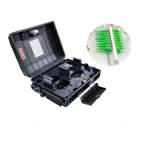
Meanwhile, when testing weak light on the ONU at the user end and testing the fiber optic distribution box link in the hallway, 70% of the optical power is indeed normal in the splitter distribution boxes, which indicating that only the loss in the entrance section is too high. Detail in the following table:
| Optical link | ONU power received(dBm) | Fiber distribution box power received(dBm) | Household section loss (dB) | Remark |
| 1 | -27.19 | -26.2 | 0.99 | Drop cable connection is not good |
| 2 | -29.95 | -19.9 | 10.05 | |
| 3 | -27.02 | -25.8 | 1.22 | Coupler problem |
| 4 | -27.19 | -19.7 | 7.49 | |
| 5 | -27.44 | -20 | 7.44 | |
| 6 | -27.21 | -21.4 | 5.81 | |
| 7 | -27.38 | -23.9 | 3.48 | |
| 8 | -30 | -28 | 2 | Splitter problem |
| 9 | -28.6 | -18 | 10.6 |
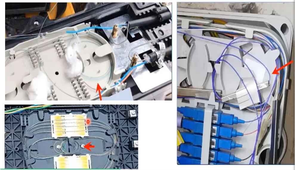
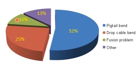
Although the distance from the user end to the optical distribution box is only a dozen or tens of meters, the average attenuation exceeds a lot, and some even exceed 10.6dB. After testing and analysis, it was found that most of the losses in the household section are caused by the bending radius being too small due to fiber optic pigtails bending and drop cable bending.
The main reasons for household section loss:
- Pigtail bending
- Drop cable bending
- Fusion splicing loss
- other
The G.652D fiber is used for fiber pigtails, and its bending radius requirement is not less than 30mm. However, in practical use, many bending radii are very small, and many may only be 5mm.
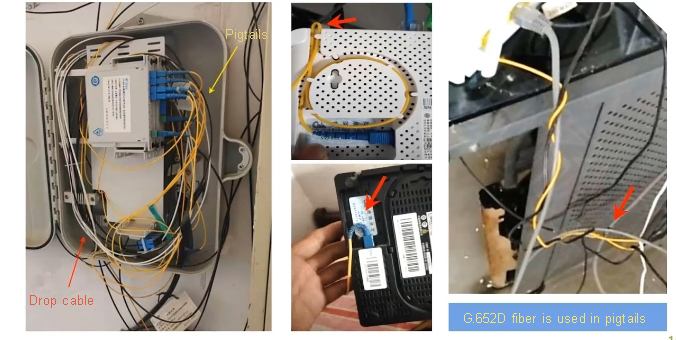
Figure 1:Fiber optic pigtails bending
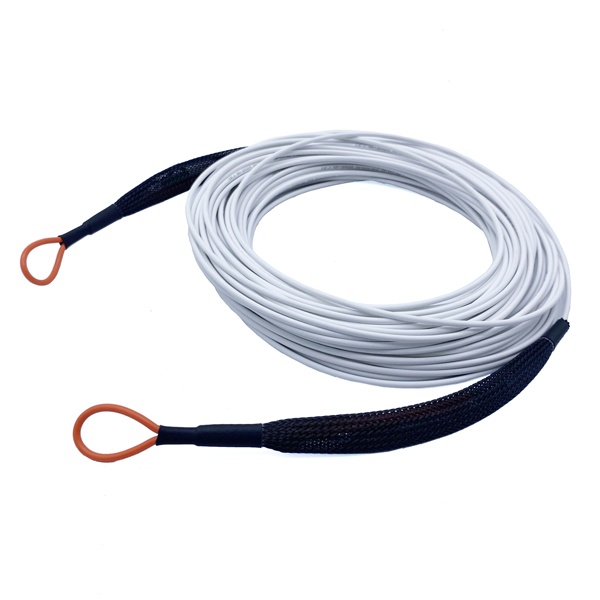
The fiber optic drop cable uses G.657A2 fiber, with a bending radius of not less than 7.5mm and a loss of not less than 0.5dB after one winding
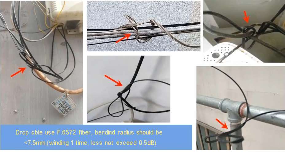
Macro bending loss test result
When the bending radius of the pigtails is less than 10mm and the bending radius of the drop cable is less than 5mm, significant macro bending loss will occur.
| Bending radius(mm) | 1490nm additional loss(dB) | |
| Pigtails (G.652D) | Drop cable (G.657A2) | |
| 10.0 | 0.18 | 0.02 |
| 7.5 | 1.6 | 0.06 |
| 5.0 | 8.13 | 0.37 |
| 3.8 | 15.61 | 0.65 |
| 2.5 | – | 7.71 |
| 1.5 | – | 6.68 |
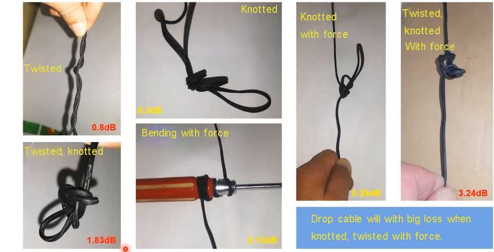
Drop cable additional loss in different simulation scenarios:
When the drop wire ftth is subjected to knotting or bending forces, the additional loss is not significant.
However, when ftth cable are twisted, knotted, and subjected to forces simultaneously, significant additional losses will occur. For example, when twisted, knotted, and subjected to force, the loss reaches 3.24 dB.
In addition, our company yingda has tested the macro bending loss of commonly used optical fibers (G.652D and G.657A2) at a wavelength of 1577nm.
The macro bending loss of G.652D fibre in ordinary cables at different wavelengths are shown in the table below.
| Test wavelength(nm) | Rolling the fiber in 10 turns | |||
| 20mm | 15mm | 10mm | 7.5mm | |
| 1577 | 0.004 | 0.051 | 7.355 | 28.193 |
| 1490 | 0 | 0.009 | 1.906 | 16.17 |
| 1310 | 0 | 0.001 | 0.079 | 1.447 |
Macro bending loss of pigtails or drop cable at end user side in different wavelength (winding fiber 1 time) are shown in the table below.
| Bending radius(mm) | Pigtails(G.652D) | Drop cable (G.657A2) | ||
| 1490nm | 1577nm | 1490nm | 1577nm | |
| 10 | 0.18 | 1.63 | 0.002 | 0.011 |
| 7.5 | 1.6 | 4.841 | 0.021 | 0.057 |
| 5 | 8.13 | 20.629 | 0.152 | 0.363 |
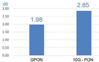
The above test results indicate that the macro bending loss of commonly used fibers is more sensitive to XG-PON. We also tested the fiber cable attenuation of approximately 150 newly installed users (XG-PON users accounting for about 35%) in a western province of a certain operator. The fiber optic cable attenuation of XG-PON users was on average 0.87dB higher than that of GPON users.
Although the macro bending loss of commonly used optical fibers is more sensitive to XG-PON, no significant weak light was found in XG-PON users during installation compared to GPON. This is mainly due to the fact that the transmission power of XG-PON optical modules is 1dB higher than that of GPON, and the receiving sensitivity of XG-PON’s ONU has also increased from GPON’s -27dBm to -28dBm.
Final suggestions:
- Macro bending loss is the main cause of weak light in ONU. When the downlink loss of ODN link exceeds the uplink loss, it must be caused by the macro bending loss of the fiber in the link.
- During the completion and acceptance of the project, it is necessary to use corresponding wavelengths to test the upstream and downstream losses of the ODN link. The upstream loss should be at least 0.1dB/km higher than the downstream loss;
- The downstream of 10G-PON uses a longer wavelength of 1577nm than 1490nm, which is more sensitive to bending loss. Excessive fiber red ball loss will have a negative impact on the application of 10G-PON.
- It is recommended to use G.657 fiber for all newly built optical cables in the access network, and to use G.657B3 fiber optic cables with better bending resistance as much as possible for the entrance section. G.652D pigtails should not be used in the entrance section, but to use drop cable patch cords or pigtails instead.
- Drop cables should avoid twisting and being subjected to force after knotting during installation.
- After the household cable is spliced at the end, the quality of the joint should be checked with a red light pen, and the attenuation of the household drop cable should be tested.
- Unused connectors without dust caps can cause significant damage and should be promptly covered with dust caps. If possible, configure a dedicated dust cap storage device.
- Fiber optic links with normal ODN attenuation and an attenuation maintenance margin exceeding 5dB do not require upgrading the optical module to Class C++.
- The transmission distance has a relatively small impact on the attenuation of the ODN link, and there is no need to solve the problem of ONU weak light sinking OLT.
Related Products