 Skip to content
 When we buy a optical passive splitter, firstly need to confirm what kind of fiber optic splitter we need and what indicators can be used as reference? What does each indicator mean?

At present, commonly used FO splitters include 1xN series and 2xN series, and their basic parameters are shown in the following table. If the customer does not raise higher requirements or objections, all our optical passive splitters are tested at the factory based on this standard.
| Split ratio | 1×2 | 1×4 | 1×8 | 1×16 | 1×32 | 1×64 | 1×128 | 2×2 | 2×4 | 2×8 | 2×16 | 2×32 | 2×64 |
| Operating Wavelength (nm) | 1260-1650 | ||||||||||||
| Fiber Type | G657A1 or customer specified | ||||||||||||
| Insertion Loss (dB) S Grade | 4.2 | 7.6 | 10.7 | 14 | 17.2 | 20.8 | 24 | 4.4 | 8 | 11 | 14.6 | 17.8 | 21 |
| Insertion Loss (dB) P Grade | 4 | 7.4 | 10.5 | 13.8 | 17 | 20.4 | 23.7 | 4.2 | 7.7 | 10.8 | 14.1 | 17.4 | 20.7 |
| Loss Uniformity(dB) | 0.6 | 0.8 | 0.8 | 1.0 | 2.0 | 2.0 | 2.0 | 0.8 | 1.0 | 1.2 | 1.5 | 1.8 | 2.0 |
| PDL (dB) | 0.2 | 0.2 | 0.3 | 0.3 | 0.3 | 0.4 | 0.5 | 0.2 | 0.2 | 0.3 | 0.3 | 0.3 | 0.4 |
| Return Loss (dB) | 55 | ||||||||||||
| Directivity (dB) | 55 | ||||||||||||
| Wavelength Dependent Loss(dB) | 0.6 | 0.8 | 0.8 | 1.0 | 1.5 | 2.0 | 0.2 | 0.8 | 1.0 | 1.2 | 1.5 | 1.8 | 2.0 |
| Operating Temperature(℃) | -40~ +85 | ||||||||||||
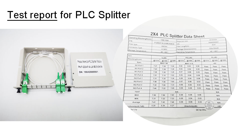
- Each splitter is 100% tested for loss and high and low temperature cycle before leaving the factory to ensure that various data parameters meet customer order requirements.
- And each product will be equipped with a corresponding English test report as below:
Core Optical Performance Parameters Of Optical Passive Splitter
Insertion loss
IL is defined as the attenuation value (dB) of the output port optical power relative to the input optical power. The calculation formula is IL=-10lg(Po/Pi)
Typical value requirements:
- 1×2 PLC Splitter: IL≤4.2 dB
- 1×32 PLC Splitter: IL ≤17.2 dB
The actual loss is strongly related to the splitting ratio. Yingda insertion loss is divided into Premium and Standard. The P-level has relatively lower loss. If the customer has no special requirements, the S-level standard will be followed.
Splitting Ratio
Split ratio is the power distribution ratio at each output port. Taper splitters (FBT splitter) or unbalanced splitters have specifications such as 50:50, 30:70, 20:80, or 10:90. Thus, the customer must specify the ratio ahead of time. Conventional PLC splitters all split evenly. For example, with a 1×2 fiber splitter, each output port receives 50% of the power at the input port; with a plc splitter 1×4, each output port receives 25% of the power at the input port; with a 1×8 plc splitter, each output port receives 12.5% of the power at the input port, and so on.
KIND NOTE:
- PLC optical passive splitters split evenly, while FBT fiber coupler support customized non-uniform splitting.
- And PLC unbalanced cable splitter like 1×9 optical splitters, have the splitting ratio directly defined on the chip, allowing for non-uniform splitting too.
Additional Loss
Addition loss is the inherent loss of the total power at all output ports relative to the input power reflects the quality of the manufacturing process. Lower values are better.
Isolation
Isolation measures the ability of an optical path to isolate signals from other optical paths. A practical requirement is ≥40 dB.
Return Loss
Return loss is the reflected light power loss, which is typically required to be ≥55 dB. Higher values can reduce interference from reflections on the light source.
Other Key Parameters Of Optical Passive Splitter
| Parameters | Definitions and Requirements | Remark |
| Loss Uniformity (dB) | Maximum deviation in insertion loss at each output port. FTB optical splitter request: ≤0.8 dB, PLC splitter differ from different ratio | Reflects the consistency of light distribution |
| Directivity (dB) | Input light leakage at non-target ports must be ≥55 dB. | Impact on signal crosstalk |
| Wavelength Polarization Dependent Loss(PDL) (dB) | Loss differences between optical signals in different polarization states should be minimized. | Key indicators for high-end applications |
| Wavelength working range | Planar lightwave circuit splitter:1260-1650nm Fused fiber coupler single-mode 1310–1550 nm, multimode 850 nm | PLC splitter are wavelength-insensitive |
| Split ratio (channels) | Planar splitter has up to 64 channels, and FBT fiber splitter has 1×2 to 1×32 channels. | Multi-channel PLCs offer significant cost advantages |
Optical Passisve Splitter Structural and Environmental Parameters
Packaging Types
- Available in bare fiber, micro steel tube, ABS box, and LGX box styles. Suitable for slot and insert installation in racks, fiber optic terminal boxes, fiber splitter boxes, and splice boxes.
Mechanical Properties
- Cable bend radius: ≥3.8 cm
- Vibration test attenuation change: <0.1 dB
- Connector mating life: >1000 cycles
Conclusion
The selection of an optical passive splitter should be determined on the specific application scenario, such as FTTH and data centers, as well as wavelength and splitting requirements and loss requirements.
- PLC splitters are suitable for wavelength-insensitive applications, with a full-band coverage of 1260-1650nm and multi-channel uniform splitting (such as PON networks).
- FBT splitters are suitable for customized splitting ratios, but they are more wavelength-sensitive and only work with one, two, or three wavelengths of 850, 1310, 1490, or 1550nm. Other wavelengths are unsuitable. At extreme split ratios, such as 1:99, insertion loss increases significantly, reaching approximately 0.16 dB for the main channel and 21 dB for the auxiliary channel.