 Skip to content
 For outdoor fiber distribution boxes, engineers have already considered the functions, usage scenarios, and various accessories that will be needed during the design of the box structure. Therefore, the factory configuration includes all the necessary installation accessories, and users do not need to purchase them separately.
However, if some customers want to save costs, they can choose to purchase some accessories locally.
Below is a brief introduction to the installation process of outdoor fiber optic boxes, including key steps and some general precautions:
Step 1: Preliminary Preparation
Fiber Optic Cable Inspection: Before construction, perform single-reel inspection of the fiber optic cable to ensure there is no damage.
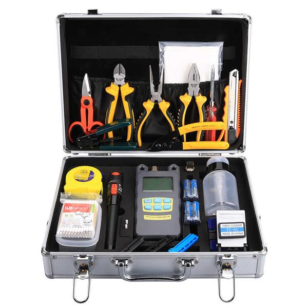
Tool Preparation: Required tools include a fusion splicer, fiber optic cleaver, waterproof tape (which stretches to twice its original length), torque wrench (maximum 2.5 N·m), etc.
Step 2: Fiber Optic Cable Fixing and Stripping
Bring the fiber optic cable into the box, stripping the outer sheath to an appropriate length (SC connector distance from the outer sheath ≤ 94.5mm), avoiding fiber bending.
Use cable ties or cable clamp to fix the fiber optic cable, leaving a 3-5mm allowance.

Step 3: Fiber Splicing and Coiling
Clean the fiber end faces before splicing with cleaning tool kits; splicing loss should be ≤ 0.08 dB/splice.
Place the splice point in the splicing tray inside the box, with a curvature radius ≥ 10 times the outer diameter of the fiber optic cable, and neatly coil the excess fiber.

Step 4: Sealing and Waterproofing Treatment
Wrapping order: First PVC tape (without stretching), then waterproof tape (stretched to cover), and finally an outer layer of PVC tape. Each layer should overlap by 1/2 and be pressed firmly.
Check the sealing to ensure the rubber ring(in red/white/black ) is not exposed.
Step 5: Grounding and Fixing
Overhead or ground-mounted installations require grounding wire; grounding resistance ≤ 10Ω, and the grounding wire cross-sectional area ≥ 16mm² copper wire.
Wall-mounted installations require fixing with expansion bolts; direct burial installations require armored protection.

Step 6: Testing and Acceptance
Use a red light pen (visual fault locator VFL) to test link connectivity, and a fiber microscope to check the cleanliness of the end faces.
Record the splicing loss values, ensuring they meet design requirements.

Fiber Optic Tools Needed


Related Fiber Optic Products


Precautions
A U-shaped expansion loop should be reserved every 3-5 utility poles for overhead fiber optic cables (approximately 15 meters/kilometer).
A concrete cover plate must be added above the buried splice box for protection.