Skip to content


Description
2×16 Fiber Splitter Features
- Low Insertion loss
- Low PDL
- Compact Design
- Good channel-to-channel uniformity
- High Reliability and Stability
- Conforms to Telcordia GR-1209&GR-1221, ROHS
2×16 Fiber Splitter Specification
| Parameters | 2×16 |
| Operating Wavelength(nm) | 1260~1650 |
| Insertion Loss (dB)(P/S Grade) | 14.4/14.6 |
| Loss Uniformity(dB) | 1.5 |
| Return Loss (dB)(P/S Grade) | 55/50 |
| Polarization Dependent Loss(dB) | 0.3 |
| Directivity (dB) | 55 |
| Wavelength Dependent Loss(dB) | 0.5 |
| Temperature Stability(-40~8℃)(dB) | 0.5 |
| Operating Temperature(℃) | -40~85 |
| Storage Temperature(℃) | -40~85 |
Detailed Display of 2×16 Fiber Splitter
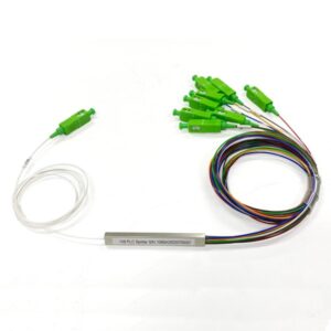
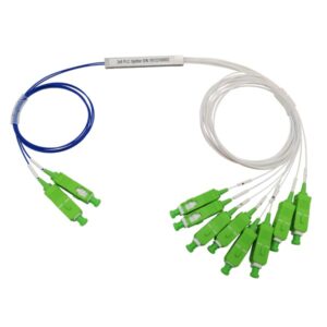
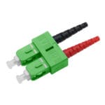
There are 2 input connectors and 16 output connectors as per the “2X16” configuration. The connectors shown are SC/APC connectors, identified by their green color. SC connectors are widely used in fiber-optic systems for their ease of use and good performance. The APC polish on the ferrule provides a better return loss performance, which is important for minimizing signal reflections in optical networks.
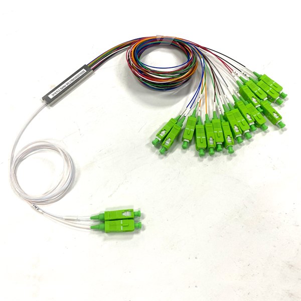
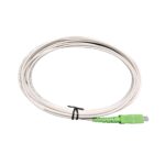
The fibers are color-coded, which is a standard practice in fiber-optic cabling. The color coding helps in identifying and managing different fibers during installation, maintenance, and troubleshooting. Common color codes follow industry standards such as TIA/EIA-598. For example, the colors may include blue, orange, green, brown, etc. Each color-coded fiber is used to connect to a specific port, and the color helps technicians quickly recognize and route the fibers correctly.
Moreover, the metal component in the middle is the PLC splitter chip module. This is the core part of the device where the optical splitting function occurs. The PLC technology allows for precise and stable splitting of optical signals through the use of waveguide structures fabricated on a planar substrate (usually silicon or silica).

The 2X16 splitter has a splitting ratio that determines how the optical power is distributed among the output fibers. Ideally, in a perfect splitter, the power from each input is evenly split among the 16 outputs. However, in practice, there may be some minor deviations, which are usually specified by the manufacturer. The splitting ratio is an important parameter as it affects the signal strength at each output port, which in turn impacts the maximum reach and the number of devices that can be supported in the optical network.
Recommended Products
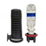 |  |  |
| GJS-DR02A Fiber Optic Splice Closure 96 Core | Dual SC Connector 2.0mm 3.0mm Univeral SMF APC | SC-APC SM SX Single Mode Fiber Optic Pigtail |