Skip to content
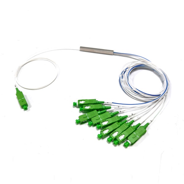


Description
90 10 Optical Splitter Features
- Low insertion loss and high return loss
- PDL automatic screening system(Ultra low PDL is available)
- High reliability and stability
- Connector can up to grade B
- 100% 3D tested by Daisi and Sumix
- High-low temperature cycle test
- 100% test before delivery
- FTTH Cabling solution could be design
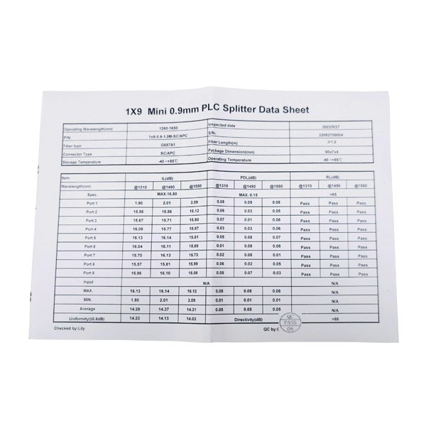
90 10 Optical Splitter Specification
| Split ratio (%) | 85/15 | 80/20 | 70/30 | 60/40 | |
| Operating wavelength (nm) | 1260-1650 | ||||
| Fiber type | G657A or customized | ||||
| IL max(dB) | channel 1 | 1.6 | 1.8 | 2.1 | 2.7 |
| channel 2-9 | 21.0 | 18.6 | 16.5 | 15.1 | |
| IL uni(dB) | Channel 2-9 | 1.8 | 1.8 | 1.8 | 1.8 |
| Return loss (dB) | ≥55 | ||||
| Directivity (dB) | ≥55 | ||||
| PDL (max.) | 0.3 | 0.3 | 0.3 | 0.3 | |
| Uniformity (max.) | 0.8 | 0.8 | 0.8 | 0.8 | |
| Wavelength dependent loss (dB) | ≤0.3 | ||||
| TDL (max.) | 0.5 | ||||
| Operating temperature | -40 ~+85 | ||||
| Storage temperature | -40 ~+85 | ||||
| Dimension (mm) / LXWXH | Bare fiber steel tube | 60x7x4 | 60x7x4 | 60x7x4 | 60x7x4 |
| 900um steel tube | 60x7x4 | 60x7x4 | 60x7x4 | 60x7x4 | |
| ABS box | 120x80x18 | 120x80x18 | 120x80x18 | 120x80x18 | |
Details of 90 10 Optical Splitter
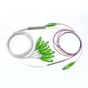
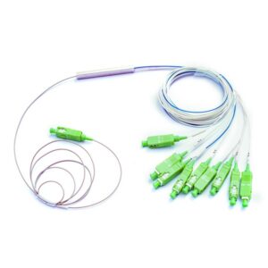
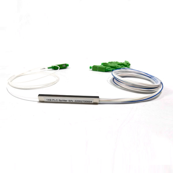
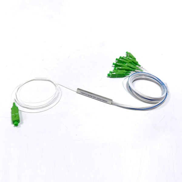
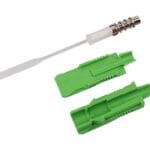
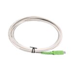
This unbalanced splitter 1×9 90%/10% consists of an input fiber, a splitter module (the metallic component in the middle), and nine output fibers. The input fiber is used to introduce the optical signal, and the splitter module performs the power splitting function, distributing the signal to the nine output fibers with different power ratios.
Among those nine output fibers, eight fibers are designed to receive 10% of the split optical power, and one fiber receives 90% of the power. The green connectors on the output fibers are typically SC/APC connectors, which are widely used in optical communication for their good return loss performance.

The numbers on the fibers serve as identifiers. They help in distinguishing between different output fibers, especially to identify which fibers are the 10% power output fiber and which one is the 90% power output fibers. This is crucial for proper installation and maintenance, ensuring that the optical signal is routed to the correct destinations according to the power requirements.

This ratio is useful in applications where different parts of a system require different optical power levels, such as in optical monitoring or in systems where one branch needs less power for specific purposes while the majority of the power is used for main data transmission.
Recommended Products
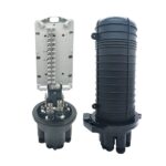 |  |  |
| High Performance GJS-D033 Optic Fiber Splice Closure | Optical SC APC Connector 2.0mm | SC-APC SM SX Single Mode Fiber Optic Pigtail |