Skip to content
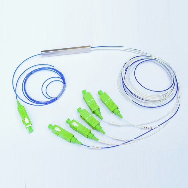
Description
PLC Planar Lightwave Circuit Features
- Low insertion loss and high return loss
- PDL automatic screening system(Ultra low PDL is available)
- High reliability and stability
- Connector can up to grade B
- 100% 3D tested by Daisi and Sumix
- High-low temperature cycle test
- 100% test before delivery
- FTTH Cabling solution could be design
PLC Planar Lightwave Circuit 1:5 85%/15% Specification
| Split ratio (%) | 85/15 | |
| Operating wavelength (nm) | 1260-1650 | |
| Fiber type | G657A or customized | |
| IL max(dB) | channel 1 | 1.7 |
| channel 2-5 | 16.5 | |
| IL uni(dB) | Channel 2-5 | 1.8 |
| Return loss (dB) | ≥55 | |
| Directivity (dB) | ≥55 | |
| PDL (max.) | 0.3 | |
| Uniformity (max.) | 0.8 | |
| Wavelength dependent loss (dB) | ≤0.3 | |
| TDL (max.) | 0.5 | |
| Operating temperature | -40 ~+85 | |
| Storage temperature | -40 ~+85 | |
| Dimension (mm) / LXWXH | Bare fiber steel tube | 60x7x4 |
| 900um steel tube | 60x7x4 | |
| ABS box | 120x80x18 | |
Details of PLC Planar Lightwave Circuit 1:5 85%/15%
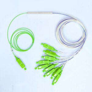
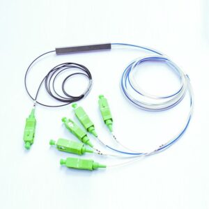
This product features a planar lightwave circuit chip at its core, which enables precise optical signal splitting. The splitter has one input port and five output ports. The input port is typically equipped with a connector (the green SC/APC connector) for easy connection to an incoming optical fiber.

Each of the five output ports also has connectors (matching the input connector type for compatibility) to distribute the optical signal. The power distribution is set at 85% to one output and 15% to the remaining four outputs, allowing for asymmetric splitting of the optical power, which can be useful in various optical communication and networking applications where different power levels to multiple destinations are required. The cables are typically made of optical fiber with appropriate shielding and protection to ensure signal integrity during transmission.
Recommended Products
 |  |  |
| Optical SC APC Connector 2.0mm | 8+1CH CWDM fiiber1470~1610nm Add Drop | SC-APC SM Fiber Pigtail 0.9mm SX 12 Color Options |