 Skip to content
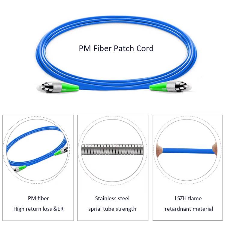
 PM fiber patch cord is a special type of fiber patch cord cable. During production, our company strictly adheres to ISO quality management system and fiber patch cord cable quality control and inspection procedures to ensure that customers receive high-quality products.
The following briefly summarizes the complete testing process and key indicators for polarization-maintaining patch cables. Hope this will be helpful.
1. Test standard and equipment
Yingda will adopt the imported high quality brand polarization extinction ratio tester (such as Shenzhen High-Tech PER tester), 3D interferometer (such as Thorlabs interferometer) and Optical time domain reflectometer (OTDR) for IL testing of long-distance patch cables.
All test standards will conforms to IEC 61755-3-31 (end face geometry) and TIA-568 (insertion loss ≤ 0.75dB).
2. Core Performance Test Items
Polarization Extinction Ratio (PER) Test
- Test Method: Use a polarization analyzer or dedicated test equipment (such as the Shenzhen High-Tech Polarization Extinction Ratio Tester) to measure the fast-axis and slow-axis optical power ratio and calculate the PER value (typically required to be ≥30dB @ 1550nm).
- Significance: A higher PER value indicates stronger polarization-maintaining performance, making it suitable for high-precision applications such as fiber optic gyroscopes and quantum communications.
Insertion Loss (IL) and Return Loss (RL) Test
- IL Test: Use an optical power meter to measure the input/output optical power difference. For telecom-grade patch cables, the requirement is ≤0.3dB.
- RL Test: Evaluate the end-face reflectance. For APC patch cord, the requirement is ≥60dB (approximately 15dB for uncoated patch cables).
Beat Length and Birefringence Testing
- Beat length measurement: Use interferometry or a spectrum analyzer. Spatial resolution must be ≤1mm and repeatability must be <5%.
- Birefringence: This indirectly reflects polarization-maintaining capability and should be evaluated in conjunction with PER testing.
3. Endface and Geometric Parameter Inspection
3D Interferometer Testing
- Radius of Curvature: 10-25mm for PC patch cord, 5-15mm for APC patch cord. Avoid air gap-induced losses.
- Vertex Offset: Required to be ≤50μm. Excessive offset can lead to unstable connections.
- Fiber Height: Range -250-+250nm. Ensure proper mating pressure.
Endface Cleanliness Inspection
Use a microscope to inspect for scratches and contamination. Contaminants can reduce RL (e.g., dust can reduce RL by more than 10dB).
4. Environmental and Mechanical Stability Testing
- Temperature Cycling Test: This simulates a -40°C to +85°C environment with a temperature ramp rate of 5°C/min to verify the stability of the PER and IL values of PM fiber patch cord.
- Tension and Bending Test: This tests the device against a standard tensile force (e.g., 5N) and a bending radius (e.g., 30mm) to determine if the PM fiber patch cord attenuation change exceeds the specified value.
For more detailed testing procedures, please refer to the manufacturer’s documentation or professional tutorials. SEND INQUIRY.