 Skip to content
 With over a decade of experience in passive fiber splitter production and development, Yingda boasts extensive experience in practical management, quality control, and R&D capabilities, enabling us to quickly meet a wide range of customer customization needs, including product labeling, logo printing, packaging, and splitting ratios.
This article explains the general process and basis for splitting ratio customization, hoping to assist you in the initial stages of your design process.
GET IN TOUCH
SEND INQUIRY
Passive Fiber Splitter Customization Process
The customization of the splitting ratio of the passive fiber splitter needs to comprehensively consider the actual link requirements and optical characteristics, and mainly follow the following principles and processes:
Step 1: Requirements Analysis
Measure the distance between each node and determine the primary/secondary service weights.
Step 2: Submit technical requirments to the fiber optic splitter factories
Provide customized splitting ratio requirements (e.g., 15%:30%:55%). The optical fiber splitter manufacturers will implement the splitting ratio using fused broaching (FBT) or planar lightguide (PLC) processes, with a splitting ratio error within ±0.5%.
Step 3: Acceptance Testing
Use an optical power meter to measure input/output power to verify that the actual splitting ratio matches the design.
Passive Fiber Splitter Customization Basis
Transmission Distance Differences
The longer the distance between optical nodes, the greater the optical power required to compensate for line losses. For example, for long-distance trunk links, a higher splitting ratio (e.g., 70%-80%) should be allocated, while shorter-distance branch links should be allocated a lower ratio (e.g., 10%-20%).
Service Priority
Critical services (e.g., data exchange) require higher optical power to ensure signal quality, while less important services (e.g., data auditing) can be allocated a lower ratio. Typical scenarios use unequal splitting ratios of 1:9 PLC splitter or 2×8 PLC splitter.


Passive Fiber Splitter Design Method
Splitting Ratio Calculation
Formula: ki = Pi / SP * 100%
Where Pi is the required drive power for each optical branch, and SP is the total required power for all branches carried by the laser.
For example: If the backbone requires 9mW and the audit requires 1mW, the splitting ratio for a 1×2 passive fiber splitter is 90%:10%.

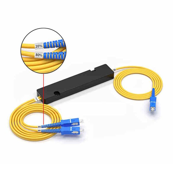
During use, if the light is not evenly split, the splitting ratio is usually indicated.
For example: 1:9 PLC Splitter 70%:30%. During the actual production process, we will indicate the splitting ratio on the product itself, label, instruction manual, or steel pipe for customer identification.


Loss Control
Insertion Loss: IL = −10lg(ki) = -10lg(Po/Pi)
Where Po is the optical power at the output, and Pi is the optical power at the input. Po/Pi is equivalent to the splitting ratio, ki, of the splitter.
For example: 1×2 passive fiber splitter 20%:80% split ratio would theoretically have an insertion loss of -10lg(20%), approximately 6.99dB.
Note: Power margin must be reserved to ensure the farthest node receives the required optical power.
Conclusion
The splitting ratio should firstly consider the distance, then service. This ratio is determined through power calculations and implemented by the manufacturer through precision machining. Finally, field testing is required to ensure balanced optical power at each node.
- For simple splitting below 1:4, a fused-bent tapered (FBT) passive fiber splitter is generally used. For splitting ratios of 1:8, 1:16, 1:32, or higher, a planar lightguide (PLC) passive fiber splitter is recommended.
- Total link loss must meet the following requirements: Transmitted optical power + splitter loss + fiber loss ≤ receive sensitivity.