 Skip to content
 Due to the special characteristics of polarization maintaining patchcord, it’s important to distinguish between the fast axis and slow axis during docking, avoiding rotation or tilting to prevent polarization shifts and signal attenuation.
Below article will discuss some key operational points based on technical principles, which maybe helpful to you. If any further questions, please feel free to contact us.
1. Pre-connection Preparations
Confirm the patch cable type and connector.
- Check that the patch cable endface type (PC/UPC/APC) matches the optical module. APC endfaces are used in highly reflective environments.
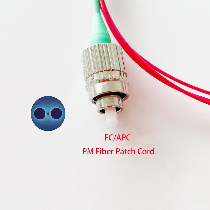
- Verify the connector type (e.g., LC, SC, FC, etc.) to ensure compatibility with the device port.
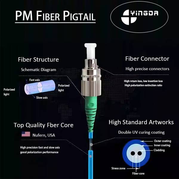
Identify the orientation of the fast and slow axes.
Polarization maintaining patchcords maintain polarization between the fast axis (low refractive index) and the slow axis (high refractive index). We must ensure that the PM patchcord markings (e.g., colored dots or notches) align with the device port.
2. Connection Steps and Precautions
Alignment and Insertion
- Align the polarization maintaining patchcord connector’s keying notch (e.g., the ridge on an LC connector) with the corresponding position on the device port. Insert the patch cord vertically until it snaps securely into place.
- Avoid rotation or tilting to prevent polarization shift and signal attenuation.
Polarity Matching (MPO Patch Cords)
- If using an MPO patch cord, connect according to the Type A/B/C polarity rules to ensure the core sequence matches the device port.
Securing and Protecting
- After connection, gently pull the PM patchcord to confirm it is secure. Avoid external forces that may cause microbend loss in the fiber.
3. Common Problems and Solutions
- Excessive signal attenuation: Check the endface for cleanliness. APC endfaces require a dedicated cleaning tool.
- Decreased polarization extinction ratio: Realign the fast and slow axes or replace the PM patchcord (extinction ratio ≥ 30dB is acceptable).
For more information on polarization maintaining patchcord technical specifications (such as beat length and birefringence) or actual application examples, please refer to the manufacturer’s documentation or professional tutorials.